MAIN BODY ECU INSTALLATION

-
INSTALL MAIN BODY ECU (MULTIPLEX NETWORK BODY ECU)
Note
-
Make sure that no foreign matter gets on the connecting surfaces.
-
Do not touch the ECU connector.
-
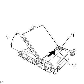
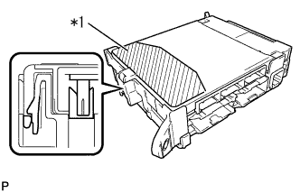
Text in Illustration *1 Housing Sidewall *2 Main Body ECU (multiplex network body ECU) Guide *a 20° Insert the main body ECU (multiplex network body ECU) up to the position where it contacts the housing sidewall of the guide as shown in the illustration.
Tech Tips
Make sure to keep the angle 20° or more as shown in the illustration.
-
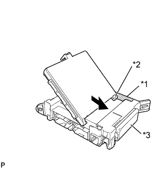
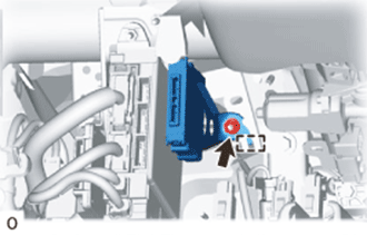
Text in Illustration *1 Housing Sidewall *2 Side A Contact Portion *2 Junction Block Fuse Slide the guide of the main body ECU (multiplex network body ECU) along the housing sidewall so that it contacts the junction block fuses as shown in the illustration.
-
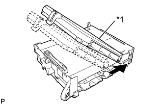
Text in Illustration *1 Side A Contact Portion Slide the the main body ECU (multiplex network body ECU) as shown in the illustration.
-
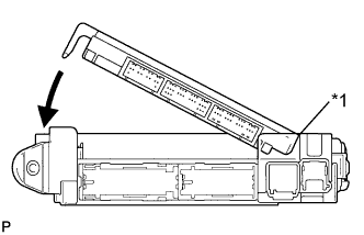
Text in Illustration *1 Side A Contact Portion While keeping the main body ECU (multiplex network body ECU) in contact with side A of the junction block (axis of rotation), rotate it downward as shown in the illustration.
-
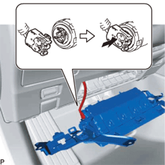
Text in Illustration *1 Push Area Press the push area until the claw engages to install the main body ECU (multiplex network body ECU).
Note
-
Make sure to press only the push area.
-
Confirm the engagement of the main body ECU (multiplex network body ECU) and junction block by listening for the lock sound.
Tech Tips
If a lock sound cannot be heard, visually check the lock part engagement. The engagement can also be confirmed if the main body ECU (multiplex network body ECU) and junction block are flush.
-
-
-
INSTALL COWL SIDE JUNCTION BLOCK LH
-
Connect the 2 connectors.
Note
Be sure to connect each connector securely.
-
Install the instrument panel cowl side junction block LH with the bolt and nuts.
- Torque:
- nut
- 8.0 N*m { 82 kgf*cm, 72 in.*lbf }
- bolt
- 13 N*m { 133 kgf*cm, 10 ft.*lbf }
-
Connect the 7 connectors.
Note
Be sure to connect each connector securely.
-
w/ VGRS:
-
Attach the 2 clamps.
-
Connect the 5 connectors.
-
-
for AWD:
-
Attach the clamp.
-
Connect the 2 connectors.
-
-
for 2WD, w/o VGRS:
-
Attach the clamp.
-
Connect the connector.
-
-
-
INSTALL CLEARANCE WARNING ECU ASSEMBLY
-
for LHD:
-
Attach the guide to install the clearance warning ECU assembly.
Note
Avoid any impact to the clearance warning ECU.
-
Install the nut.
-
Connect the connector.
-
-
for RHD:
Attach the 2 claws to install the clearance warning ECU assembly.
-
-
INSTALL NO. 1 LOWER INSTRUMENT PANEL AIRBAG ASSEMBLY (for LHD)
-
Check that the engine switch is off.
-
Check that the cable is disconnected from the negative (-) battery terminal.
CAUTION:
Wait at least 90 seconds after disconnecting the cable from the negative (-) battery terminal to disable the SRS system.
-
Connect the airbag connector to the lower No. 1 instrument panel airbag assembly.
Note
When connecting any airbag connector, take care not to damage the airbag wire harness.
-
Push in the lock to install the airbag connector.
-
Attach the 3 claws to connect the hood lock control lever sub-assembly to the lower No. 1 instrument panel airbag assembly.
-
Temporarily install the lower No. 1 instrument panel airbag assembly with the hook and pin.
-
Install the lower No. 1 instrument panel airbag assembly with the 4 bolts.
- Torque:
- 10 N*m { 102 kgf*cm, 7 ft.*lbf }
Note
Confirm that the lower No. 1 instrument panel airbag assembly is installed securely without any excessive gaps and is not protruding outward.
-
-
INSTALL NO. 1 INSTRUMENT PANEL GARNISH SUB-ASSEMBLY (for LHD)
-
Attach the 4 clips to install the No. 1 instrument panel garnish sub-assembly.
-
-
INSTALL NO. 1 INSTRUMENT PANEL SAFETY PAD SUB-ASSEMBLY (for LHD)
-
Connect the connectors.
-
Attach the 9 clips and guide to install the No. 1 instrument panel safety pad sub-assembly.
-
-
INSTALL GLOVE COMPARTMENT DOOR ASSEMBLY (for RHD)
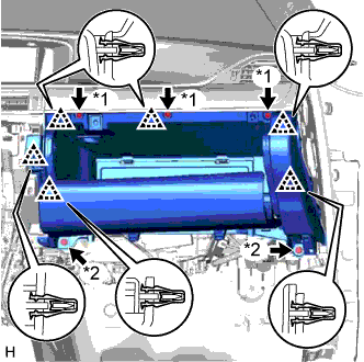
Text in Illustration *1 Screw <A> *2 Bolt <E>
-
Connect the connectors and attach the clamp.
-
Attach the 6 clips to install the glove compartment door assembly.
-
Install the 3 screws <A> and 2 bolts <E>.
-
-
INSTALL NO. 2 INSTRUMENT PANEL UNDER COVER SUB-ASSEMBLY (for RHD)
-
Connect the connectors and attach the clamp.
-
Attach the 5 clips and 2 guides to install the No. 2 instrument panel under cover sub-assembly.
-
-
INSTALL CENTER INSTRUMENT CLUSTER FINISH PANEL
-
Connect the connector.
-
Attach the 9 clips and guide to install the center instrument cluster finish panel.
-
-
INSTALL INSTRUMENT PANEL FINISH PANEL END LH
-
Attach the 5 clips and 2 guides to install the instrument panel finish panel end LH.
-
-
INSTALL INSTRUMENT SIDE PANEL LH
-
Attach the 7 clips to install the instrument side panel LH.
-
-
INSTALL FRONT DOOR OPENING TRIM COVER LH
-
Attach the 5 claws to install the front door opening trim cover LH.
Note
After installing the front door opening trim cover LH, make sure that the lip of the front door opening trim weatherstrip LH is not pinched.
-
-
INSTALL FRONT DOOR SCUFF PLATE LH
-
Attach the 10 claws and 4 clips to install the front door scuff plate LH.
-
-
CONNECT CABLE TO NEGATIVE BATTERY TERMINAL
Note
When disconnecting the cable, some systems need to be initialized after the cable is reconnected Click here.