NIGHT VIEW SYSTEM, Diagnostic DTC:B2816, B2817

| DTC Code | DTC Name |
|---|---|
| B2816 | Near Infrared Radiation Floodlight RH |
| B2817 | Near Infrared Radiation Floodlight LH |
DESCRIPTION
The No. 1 night view ECU monitors the status of the left and right near-infrared ray emitters. When an operation malfunction signal for a near-infrared ray emitter is detected, a DTC is stored.
Tech Tips
While DTCs are stored, the night view system does not operate and a warning message is displayed on the accessory meter assembly.
| DTC Code | DTC Detection Condition | Trouble Area |
|---|---|---|
| B2816 | The No. 1 night view ECU detects an operation malfunction signal for the near-infrared ray emitter on the right side. |
|
| B2817 | The No. 1 night view ECU detects an operation malfunction signal for the near-infrared ray emitter on the left side. |
|
-
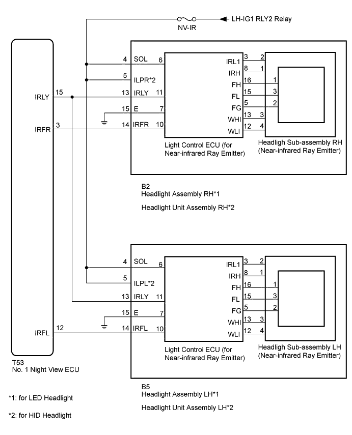
*1: for LED Headlight
-
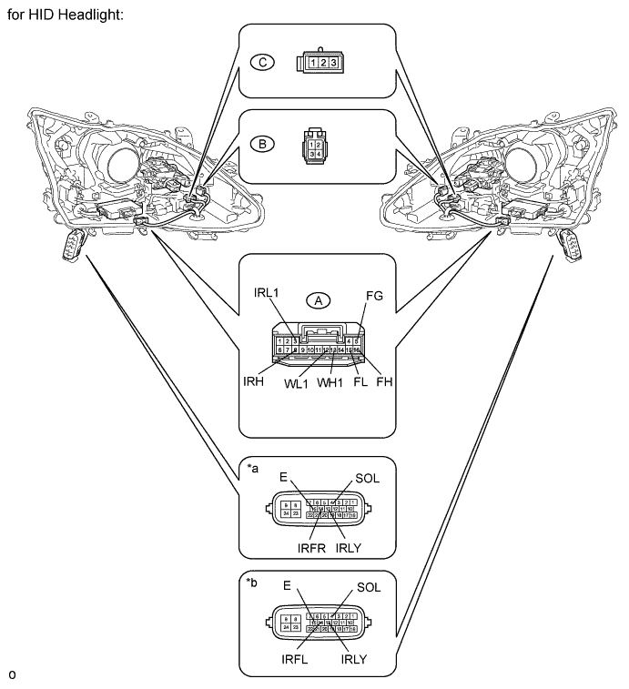
*2: for HID Headlight
WIRING DIAGRAM
INSPECTION PROCEDURE
Note
-
When the No. 1 night view ECU is replaced, perform night view camera adjustment Click here.
-
Inspect the fuses for circuits related to this system before performing the following inspection procedure.
PROCEDURE
-
CHECK HARNESS AND CONNECTOR (HEADLIGHT ASSEMBLY - BATTERY AND BODY GROUND)
-
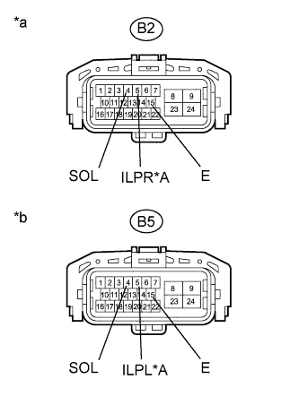
Text in Illustration *A for HID Headlight *a Front view of wire harness connector
(to Headlight Assembly RH)
*b Front view of wire harness connector
(to Headlight Assembly LH)
Disconnect the headlight assembly connector.
-
Measure the voltage according to the value(s) on the table below.
Standard Voltage RH Side Tester Connection Switch Condition Specified Condition B2-4 (SOL) - Body ground Ignition switch on (IG) 11 to 14 V B2-5 (ILPR) - Body ground* LH Side Tester Connection Switch Condition Specified Condition B5-4 (SOL) - Body ground Ignition switch on (IG) 11 to 14 V B5-5 (ILPL) - Body ground*
-
*: for HID Headlight
-
-
Measure the resistance according to the value(s) in the table below.
Standard Resistance RH Side Tester Connection Condition Specified Condition B2-15 (E) - Body ground Always Below 1 Ω LH Side Tester Connection Condition Specified Condition B5-15 (E) - Body ground Always Below 1 Ω
NG 
REPAIR OR REPLACE HARNESS OR CONNECTOR
OK 
-
-
CHECK HARNESS AND CONNECTOR (HEADLIGHT ASSEMBLY - NO. 1 NIGHT VIEW ECU)
-
Disconnect the B2*1 or B5*2 headlight assembly connector.
-
*1: RH Side
-
*2: LH Side
-
-
Disconnect the T53 No. 1 night view ECU connector.
-
Measure the resistance according to the value(s) in the table below.
Standard Resistance RH Side Tester Connection Condition Specified Condition B2-13 (IRLY) - T53-15 (IRLY) Always Below 1 Ω B2-14 (IRFR) - T53-3 (IRFR) B2-13 (IRLY) - Body ground Always 10 kΩ or higher B2-14 (IRFR) - Body ground LH Side Tester Connection Condition Specified Condition B5-13 (IRLY) - T53-15 (IRLY) Always Below 1 Ω B5-14 (IRFL) - T53-12 (IRFL) B5-13 (IRLY) - Body ground Always 10 kΩ or higher B5-14 (IRFL) - Body ground
NG
REPAIR OR REPLACE HARNESS OR CONNECTOR
OK
-
-
CHECK NO. 1 NIGHT VIEW ECU
-
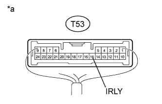
Text in Illustration *a Component with harness connected
(No. 1 Night View ECU)
Using the GTS, follow the instructions to switch to the "Night View" screen and select "Active Test".
-
Select "Night View System Operation" on the screen and forcibly operate the night view system.
-
Measure the voltage according to the value(s) in the table below.
Standard Voltage Tester Connection Condition Specified Condition T53-15 (IRLY) - Body ground Night view system operating (forcibly operated using Active Test) 1.27 to 1.76 V
NG
REPLACE NO. 1 NIGHT VIEW ECU Click here
OK
-
-
INSPECT HEADLIGHT ASSEMBLY
-
for LED Headlight:
-
Remove the headlight assembly Click here.
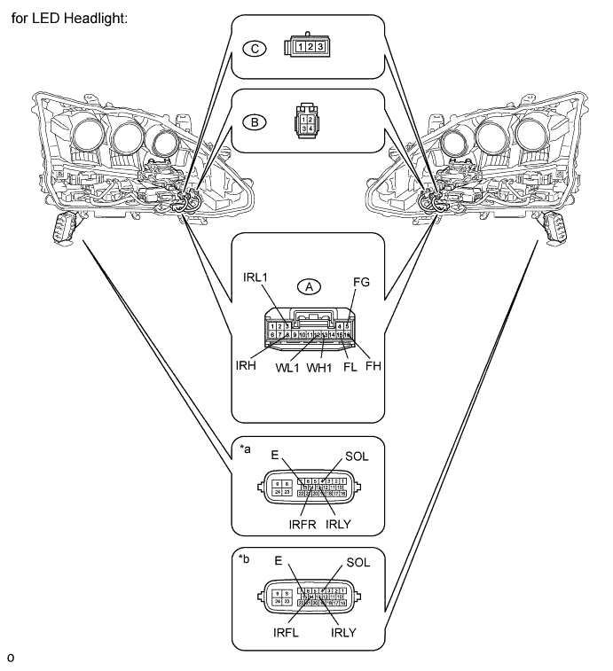
Text in Illustration *a Component without harness connected
(Headlight Assembly RH)
*b Component without harness connected
(Headlight Assembly LH)
-
Remove the headlight lens Click here.
-
Disconnect the A light control ECU (for near-infrared ray emitter) connector.
-
Disconnect the B and C headlight sub-assembly (for near-infrared ray emitter) connectors.
-
Measure the resistance according to the value(s) in the table below.
Standard Resistance for RH Tester Connection Condition Specified Condition 4 (SLO) - A-6 Always Below 1 Ω 13 (IRLY) - A-11 Always Below 1 Ω 15 (E) - A-7 Always Below 1 Ω 14 (IRFR) - A-10 Always Below 1 Ω A-3 (IRL1) - B-2 Always Below 1 Ω A-8 (IRH)- B-1 Always Below 1 Ω A-16 (FH) - C-1 Always Below 1 Ω A-15 (FL) - C-3 Always Below 1 Ω A-5 (FG) - C-2 Always Below 1 Ω A-13 (WH1) - B-3 Always Below 1 Ω A-12 (WL1) - B-4 Always Below 1 Ω for LH Tester Connection Condition Specified Condition 4 (SLO) - A-6 Always Below 1 Ω 13 (IRLY) - A-11 Always Below 1 Ω 15 (E) - A-7 Always Below 1 Ω 14 (IRFL) - A-10 Always Below 1 Ω A-3 (IRL1) - B-2 Always Below 1 Ω A-8 (IRH)- B-1 Always Below 1 Ω A-16 (FH) - C-1 Always Below 1 Ω A-15 (FL) - C-3 Always Below 1 Ω A-5 (FG) - C-2 Always Below 1 Ω A-13 (WH1) - B-3 Always Below 1 Ω A-12 (WL1) - B-4 Always Below 1 Ω
-
-
for HID Headlight:
-
Remove the headlight unit assembly Click here.
Text in Illustration *a Component without harness connected
(Headlight Unit Assembly RH)
*b Component without harness connected
(Headlight Unit Assembly LH)
-
Remove the headlight lens Click here.
-
Disconnect the A light control ECU (for near-infrared ray emitter) connector.
-
Disconnect the B and C headlight sub-assembly (for near-infrared ray emitter) connectors.
-
Measure the resistance according to the value(s) in the table below.
Standard Resistance for RH Tester Connection Condition Specified Condition 4 (SLO) - A-6 Always Below 1 Ω 13 (IRLY) - A-11 Always Below 1 Ω 15 (E) - A-7 Always Below 1 Ω 14 (IRFR) - A-10 Always Below 1 Ω A-3 (IRL1) - B-2 Always Below 1 Ω A-8 (IRH)- B-1 Always Below 1 Ω A-16 (FH) - C-1 Always Below 1 Ω A-15 (FL) - C-3 Always Below 1 Ω A-5 (FG) - C-2 Always Below 1 Ω A-13 (WH1) - B-3 Always Below 1 Ω A-12 (WL1) - B-4 Always Below 1 Ω for LH Tester Connection Condition Specified Condition 4 (SLO) - A-6 Always Below 1 Ω 13 (IRLY) - A-11 Always Below 1 Ω 15 (E) - A-7 Always Below 1 Ω 14 (IRFL) - A-10 Always Below 1 Ω A-3 (IRL1) - B-2 Always Below 1 Ω A-8 (IRH)- B-1 Always Below 1 Ω A-16 (FH) - C-1 Always Below 1 Ω A-15 (FL) - C-3 Always Below 1 Ω A-5 (FG) - C-2 Always Below 1 Ω A-13 (WH1) - B-3 Always Below 1 Ω A-12 (WL1) - B-4 Always Below 1 Ω Result Result Proceed to OK A NG (for LED Headlight) B NG (for HID Headlight) C
-
B
REPLACE HEADLIGHT ASSEMBLY Click here
C
REPLACE HEADLIGHT UNIT ASSEMBLY Click here
A
-
-
REPLACE HEADLIGHT SUB-ASSEMBLY (NEAR-INFRARED RAY EMITTER)
-
for LED Headlight:
-
Temporarily replace the headlight sub-assembly (near-infrared ray emitter) with a new or normally functioning one Click here.
-
-
for HID Headlight:
-
Temporarily replace the headlight sub-assembly (near-infrared ray emitter) with a new or normally functioning one Click here.
-
NEXT
-
-
CHECK FOR DTC
-
Clear the DTCs Click here.
-
Turn the ignition switch off.
-
Wait 6 seconds after turning the ignition switch off, and then turn the ignition switch on (IG).
-
Check for DTCs Click here.
OK DTC B2816 or B2817 is not output.
NG 
REPLACE LIGHT CONTROL ECU (FOR NEAR-INFRARED RAY EMITTER) Click here
OK 
END (HEADLIGHT SUB-ASSEMBLY [NEAR-INFRARED RAY EMITTER] IS DEFECTIVE)
-
-
REPLACE LIGHT CONTROL ECU (FOR NEAR-INFRARED RAY EMITTER)
-
for LED Headlight:
-
Temporarily replace the light control ECU (for near-infrared ray emitter) with a new or normally functioning one Click here.
-
-
for HID Headlight:
-
Temporarily replace the light control ECU (for near-infrared ray emitter) with a new or normally functioning one Click here.
-
NEXT
-
-
CHECK FOR DTC
-
Clear the DTCs Click here.
-
Turn the ignition switch off.
-
Wait 6 seconds after turning the ignition switch off, and then turn the ignition switch on (IG).
-
Check for DTCs Click here.
OK DTC B2816 or B2817 is not output.
NG
REPLACE NO. 1 NIGHT VIEW ECU Click here
OK
END (LIGHT CONTROL ECU [FOR NEAR-INFRARED RAY EMITTER] IS DEFECTIVE)
-