NIGHT VIEW SYSTEM, Diagnostic DTC:B2815

| DTC Code | DTC Name |
|---|---|
| B2815 | Low Beam Headlights do not Illuminate |
DESCRIPTION
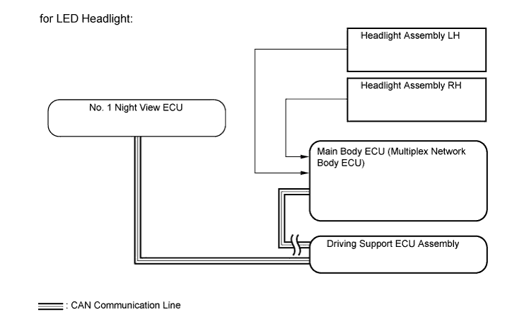
for LED Headlight:
The main body ECU monitors the low beam illumination state. If a low beam malfunction is detected, the main body ECU sends a malfunction signal to the No. 1 night view ECU via CAN communication and a DTC is stored.
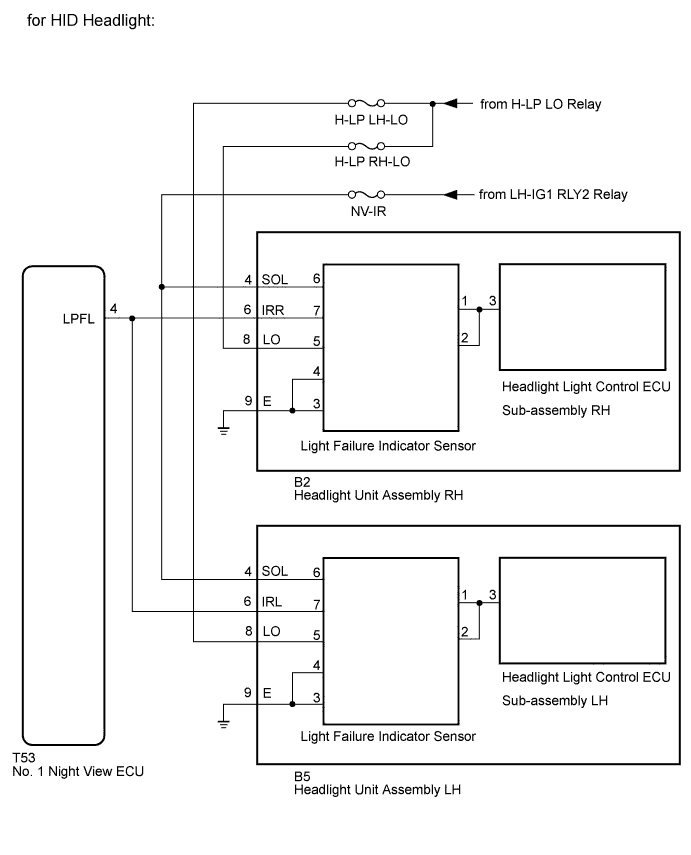
for HID Headlight:
The No. 1 night view ECU monitors the state of the low beam headlights. When a low beam headlight malfunction is detected, a DTC is stored.
Tech Tips
While DTCs are stored, the night view system does not operate and a warning message is displayed on the accessory meter assembly.
| DTC Code | DTC Detection Condition | Trouble Area |
|---|---|---|
| B2815 |
for LED Headlight: |
|
for HID Headlight: |
|
WIRING DIAGRAM
INSPECTION PROCEDURE
Note
-
When the No. 1 night view ECU is replaced, perform night view camera adjustment Click here.
-
Inspect the fuses for circuits related to this system before performing the following inspection procedure.
PROCEDURE
-
CHECK VEHICLE TYPE
-
Check the vehicle type.
Result Result Proceed to for LED Headlight A for HID Headlight B
B 
CHECK THAT THE HEADLIGHTS ILLUMINATE Click here
A 
-
-
CHECK THAT THE HEADLIGHTS ILLUMINATE
-
Check if the headlights illuminate normally when the headlight dimmer switch is operated.
OK Headlights illuminate normally.
NG 
GO TO LIGHTING SYSTEM Click here
OK
-
-
CHECK FOR DTC
-
Connect the GTS to the DLC3.
-
Turn the ignition switch on (IG) and turn the GTS on.
-
Enter the following menus: System Select / Health Check.
-
Clear the DTCs.
-
Turn the ignition switch off.
-
Wait 6 seconds after turning the ignition switch off.
-
Enter the following menus: System Select / Health Check.
-
Check for DTCs.
Result Result Proceed to DTC B2815 is output A Lighting system DTC is output B CAN communication system DTC is output (for LHD) C CAN communication system DTC is output (for RHD) D
B
GO TO LIGHTING SYSTEM Click here
C
GO TO CAN COMMUNICATION SYSTEM Click here
D
GO TO CAN COMMUNICATION SYSTEM Click here
A 
REPLACE NO. 1 NIGHT VIEW ECU Click here
-
-
CHECK THAT THE HEADLIGHTS ILLUMINATE
-
Check if the headlights illuminate normally when the headlight dimmer switch is operated.
OK Headlights illuminate normally.
NG
GO TO LIGHTING SYSTEM Click here
OK
-
-
CHECK HARNESS AND CONNECTOR (HEADLIGHT UNIT ASSEMBLY - BATTERY AND BODY GROUND)
-
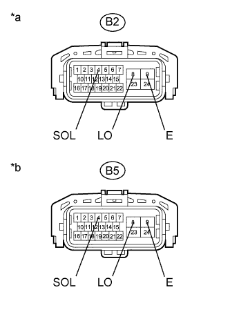
Text in Illustration *a Front view of wire harness connector
(to Headlight Unit Assembly RH)
*b Front view of wire harness connector
(to Headlight Unit Assembly LH)
Disconnect the headlight unit assembly connectors.
-
Measure the voltage according to the value(s) on the table below.
Standard Voltage RH Side Tester Connection Switch Condition Specified Condition B2-8 (LO) - Body ground Headlight dimmer switch off Below 1 V Headlight dimmer switch HEAD 11 to 14 V B2-4 (SOL) - Body ground Ignition switch on (IG) 11 to 14 V LH Side Tester Connection Switch Condition Specified Condition B5-8 (LO) - Body ground Headlight dimmer switch off Below 1 V Headlight dimmer switch HEAD 11 to 14 V B5-4 (SOL) - Body ground Ignition switch on (IG) 11 to 14 V -
Measure the resistance according to the value(s) in the table below.
Standard Resistance RH Side Tester Connection Condition Specified Condition B2-9 (E) - Body ground Always Below 1 Ω LH Side Tester Connection Condition Specified Condition B5-9 (E) - Body ground Always Below 1 Ω
NG
REPAIR OR REPLACE HARNESS OR CONNECTOR
OK
-
-
CHECK HARNESS AND CONNECTOR (HEADLIGHT UNIT ASSEMBLY - NO. 1 NIGHT VIEW ECU)
-
Disconnect the B2*1 and B5*2 headlight unit assembly connectors.
-
*1: RH Side
-
*2: LH Side
-
-
Disconnect the T53 No. 1 night view ECU connector.
-
Measure the resistance according to the value(s) in the table below.
Standard Resistance RH Side Tester Connection Condition Specified Condition B2-6 (IRR) - T53-4 (LPFL) Always Below 1 Ω B2-6 (IRR) - Body ground Always 10 kΩ or higher LH Side Tester Connection Condition Specified Condition B5-6 (IRL) - T53-4 (LPFL) Always Below 1 Ω B5-6 (IRL) - Body ground Always 10 kΩ or higher
NG
REPAIR OR REPLACE HARNESS OR CONNECTOR
OK
-
-
INSPECT HEADLIGHT UNIT ASSEMBLY
-
Remove the headlight unit assembly Click here.
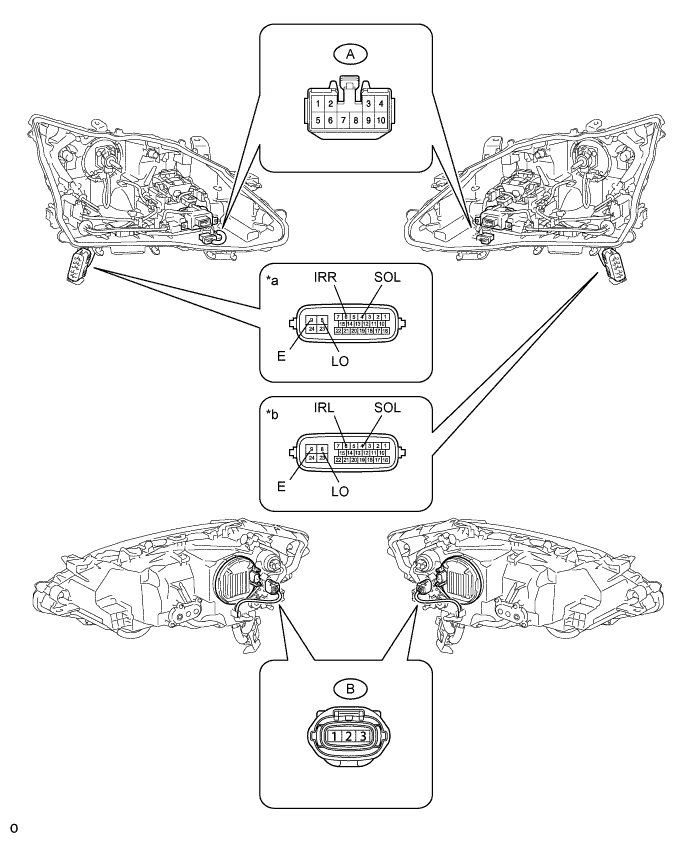
Text in Illustration *a Component without harness connected
(Headlight Unit Assembly RH)
*b Component without harness connected
(Headlight Unit Assembly LH)
-
Remove the headlight lens Click here.
-
Disconnect the A light failure indicator sensor connector.
-
Disconnect the B headlight light control ECU sub-assembly connector.
-
Measure the resistance according to the value(s) in the table below.
Standard Resistance RH Side Tester Connection Condition Specified Condition 4 (SLO) - A-6 Always Below 1 Ω 6 (IRR) - A-7 Always Below 1 Ω 8 (LO) - A-5 Always Below 1 Ω 9 (E) - A-4 Always Below 1 Ω 9 (E) - A-3 Always Below 1 Ω A-1 - B-3 Always Below 1 Ω A-2 - B-3 Always Below 1 Ω LH Side Tester Connection Condition Specified Condition 4 (SLO) - A-6 Always Below 1 Ω 6 (IRL) - A-7 Always Below 1 Ω 8 (LO) - A-5 Always Below 1 Ω 9 (E) - A-4 Always Below 1 Ω 9 (E) - A-3 Always Below 1 Ω A-1 - B-3 Always Below 1 Ω A-2 - B-3 Always Below 1 Ω
NG
REPLACE HEADLIGHT UNIT ASSEMBLY Click here
OK
-
-
REPLACE LIGHT FAILURE INDICATOR SENSOR
-
Temporarily replace the light failure indicator sensor with a new or normally functioning one Click here.
NEXT
-
-
CHECK FOR DTC
-
Clear the DTCs Click here.
-
Turn the ignition switch off.
-
Wait 6 seconds after turning the ignition switch off and then turn ignition switch on (IG).
-
Check for DTCs Click here.
OK DTC B2851 is not output.
NG
REPLACE NO.1 NIGHT VIEW ECU Click here
OK
END (LIGHT FAILURE INDICATOR SENSOR IS DEFECTIVE)
-
-
REPLACE NO.1 NIGHT VIEW ECU
-
Temporarily replace the No. 1 night view ECU with a new or normally functioning one Click here.
NEXT
-
-
ADJUST NIGHT VIEW CAMERA ASSEMBLY
-
Perform night view camera adjustment Click here.
NEXT
-
-
CHECK FOR DTC
-
Clear the DTCs Click here.
-
Turn the ignition switch off.
-
Wait 6 seconds after turning the ignition switch off and then turn ignition switch on (IG).
-
Wait 30 seconds after turning the headlight dimmer switch to the head position.
-
Check for DTCs Click here.
OK DTC B2851 is not output.
NG
REPLACE HEADLIGHT LIGHT CONTROL ECU SUB-ASSEMBLY Click here
OK
END (NO. 1 NIGHT VIEW ECU IS DEFECTIVE)
-