BLIND SPOT MONITOR SYSTEM, Diagnostic DTC:C1ABA

| DTC Code | DTC Name |
|---|---|
| C1ABA | Blind Spot Monitor Slave Module Connection Incorrect |
DESCRIPTION
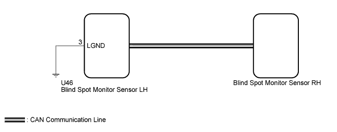
The blind spot monitor sensor LH stores this DTC when terminal No. 3 of the blind spot monitor sensor LH is not connected properly, or the blind spot monitor sensor is not installed on its correct side and the wire harness that is connected to the blind spot monitor main switch (integration control and panel assembly) is connected to terminal No. 3 of the blind spot sensor LH.
| DTC Code | DTC Detection Condition | Trouble Area |
|---|---|---|
| C1ABA | There is an open in the ground circuit (Terminal No. 3) of the blind spot monitor sensor LH for a specified period of time. |
|
WIRING DIAGRAM
INSPECTION PROCEDURE
Note
-
After completing this inspection procedure, make sure to clear the DTC.
-
When checking for DTCs, make sure that the blind spot monitor main switch (integration control and panel assembly) is on.
Tech Tips
-
Since the blind spot monitor system has functions that use CAN communication system, first confirm that there is no malfunction in the communication system by inspecting the CAN communication functions in accordance with the "How to Proceed with Troubleshooting" procedures. Then, conduct the following inspection procedure.
PROCEDURE
-
CONFIRM PART NUMBER AND IDENTIFICATION MARK
-
Confirm whether the blind spot monitor sensors are installed to the correct side or not.
-
Check if the part number and identification mark of the blind spot monitor sensor on the vehicle is correct.
OK The part number and identification mark is correct.
-
NG 
INSTALL BLIND SPOT MONITOR SENSOR TO CORRECT SIDE Click here
OK 
-
-
CHECK HARNESS AND CONNECTOR (BLIND SPOT MONITOR SENSOR LH - BATTERY AND BODY GROUND)
-
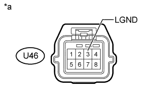
Text in Illustration *a Front view of wire harness connector
(to Blind Spot Monitor Sensor LH)
Disconnect connector from the blind spot monitor sensor LH.
-
Measure the resistance according to the value(s) in the table below.
Standard Resistance Tester Connection Condition Specified Condition U46-3 (LGND) - Body ground Always Below 1 Ω -
Measure the voltage according to the value(s) in the table below.
Standard Voltage Tester Connection Switch Condition Specified Condition U46-3 (LGND) - Body ground Engine switch on (IG) Below 1 V
NG
REPAIR OR REPLACE HARNESS OR CONNECTOR
OK 
REPLACE BLIND SPOT MONITOR SENSOR LH Click here
-