BLIND SPOT MONITOR SYSTEM SYSTEM DESCRIPTION

-
GENERAL
-
The blind spot monitor is a system that assists the driver in making the decision to change lanes. The system uses quasi-millimeter wave radar to detect vehicles that are traveling in an adjacent lane in the area that is not reflected in the outer rear view mirror assembly. The system advises the driver of the existence of a vehicle by illuminating the blind spot monitor indicator on the outer rear view mirror assembly.
-
If the turn signal is operated while the blind spot monitor indicator on an outer rear view mirror assembly is illuminated, the indicator starts blinking to give additional warning to the driver.
-
-
FUNCTION OF COMPONENTS
Component Function Blind Spot Monitor Sensor
-
Consists of a 24 GHz radar module and an integrated processing module.
-
Illuminates the outer rear view mirror indicator on the outer rear view mirror assembly when a vehicle is present in the blind spot area.
-
Changes the outer rear view mirror indicator on the outer rear view mirror assembly from illuminated to blinking when a turn signal is received from the combination meter assembly.
Outer Rear View Mirror Indicator Turns on or blinks the indicator based on a signal from the blind spot monitor sensor. Blind Spot Monitor Main Switch (Integration Control and Panel Assembly) Turns the blind spot monitor system on or off. Combination Meter Assembly
-
Sends the turn signal state from the headlight dimmer switch assembly (turn signal light switch) to the blind spot monitor sensor via CAN communication.
-
If the blind spot monitor detects a malfunction while it is operating, "Check BSM System" or "BSM not available" message is displayed in multi-information dispaly.
Main Body ECU (Multiplex Network Body ECU) Sends the destination information to the blind spot monitor sensor via CAN communication. Brake Actuator Assembly Transmits a vehicle speed signal to the blind spot monitor sensor via CAN communication. ECM Sends shift position signal (R) and HV flag to the blind spot monitor sensor via CAN communication. Spiral with Sensor Cable Sub-assembly Detects the angle of the steering wheel and sends the resulting signals to the blind spot monitor sensor via CAN communication. -
-
OPERATION DESCRIPTION
-
Operation conditions of the blind spot monitor system
-
The blind spot monitor main switch (integration control and panel assembly) is on.
-
Vehicle speed is more than approximately 40 km/h (25 mph).
-
-
Conditions in which a sensor can detect a vehicle
The blind spot monitor system indicates detection of a vehicle in the detection area when either condition is met:
-
When a vehicle is detected in an adjacent lane overtaking this vehicle.
-
When another vehicle is detected entering the detection area because it changed lanes.
-
-
Detection area
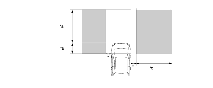
Text in Illustration *a Within approximately 3 m (9.84 ft) behind the rear bumper *b Within approximately 1 m (3.28 ft) forward of the rear bumper *c Within approximately 3 m (9.84 ft) from the side of the vehicle - -
-
Vehicles in the above areas can be detected:
-
*: The first 0.5 m (1.64 ft) from the side of the vehicle is not included in the detection area.
-
-
-
-
OPERATION OF OUTER REAR VIEW MIRROR INDICATOR ON OUTER REAR VIEW MIRROR ASSEMBLY
-
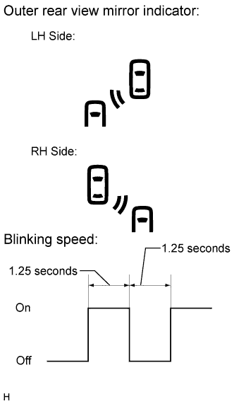
The outer rear view mirror indicator on each outer rear view mirror assembly operates as follows:
-
When the blind spot monitor main switch (integration control and panel assembly) is turned on, the outer rear view mirror indicator on each outer rear view mirror assembly illuminates for 3 seconds (initial check).
-
While the system is operating, when a sensor detects a vehicle in the blind spot area, the outer rear view mirror indicator on the outer rear view mirror assembly illuminates.
-
While the system is detecting a vehicle in the detection area and the indicator is illuminated, if the turn signal is turned on, the indicator starts blinking.
-
-