LEXUS PARKING ASSIST-SENSOR SYSTEM Clearance Warning Buzzer Circuit
DESCRIPTION
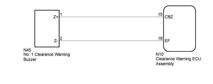
This circuit consists of a power source, the No. 1 clearance warning buzzer and clearance warning ECU assembly. An ECU-excited type buzzer is used. The battery voltage supplied through the buzzer is grounded inside the clearance warning ECU assembly using a pulsed digital pattern, producing sound. The ECU operates the buzzer using a sound pattern that changes depending on the distance to the obstacle.
WIRING DIAGRAM
INSPECTION PROCEDURE
Note
Inspect the fuse for circuits related to this system before performing the following inspection procedure.
PROCEDURE
-
PERFORM ACTIVE TEST USING GTS
-
Connect the GTS to the DLC3.
-
Turn the engine switch on (IG).
-
Turn the GTS on.
-
Enter the following menus: Body Electrical / Clearance Sonar / Active Test.
-
Check that the buzzer operates by performing the Active Test.
Clearance Sonar Tester Display Test Part Control Range Diagnostic Note Buzzer No. 1 clearance warning buzzer Operate or Stop Confirm that the vehicle is stopped and the engine switch is on (IG) OK The No. 1 clearance warning buzzer sounds.
NG 
CHECK HARNESS AND CONNECTOR (NO. 1 CLEARANCE WARNING BUZZER - CLEARANCE WARNING ECU ASSEMBLY) Click here
OK 
PROCEED TO NEXT SUSPECTED AREA SHOWN IN PROBLEM SYMPTOMS TABLE Click here
-
-
CHECK HARNESS AND CONNECTOR (NO. 1 CLEARANCE WARNING BUZZER - CLEARANCE WARNING ECU ASSEMBLY)
-
Disconnect the N10 connector from the clearance warning ECU assembly connector.
-
Disconnect the N45 connector from the No. 1 clearance warning buzzer.
-
Measure the voltage according to the value(s) in the table below.
Standard Voltage Tester Connection Condition Specified Condition N10-15 (CBZ) - N45-1 (Z+) Always Below 1 Ω N10-16 (EF) - N45-2 (Z-) Always Below 1 Ω N10-15 (CBZ) or N45-1 (Z+) - Body ground Always 10 kΩ or higher N10-16 (EF) or N45-2 (Z-) - Body ground Always 10 kΩ or higher
NG 
REPAIR OR REPLACE HARNESS OR CONNECTOR
OK 
-
-
REPLACE NO. 1 CLEARANCE WARNING BUZZER
-
Replace the No. 1 clearance warning buzzer with a new or normally functioning one Click here.
NEXT
-
-
PERFORM ACTIVE TEST USING GTS
-
Connect the GTS to the DLC3.
-
Turn the engine switch on (IG).
-
Turn the GTS on.
-
Enter the following menus: Body Electrical / Clearance Sonar / Active Test.
-
Check that the buzzer operates by performing the Active Test.
Clearance Sonar Tester Display Test Part Control Range Diagnostic Note Buzzer No. 1 clearance warning buzzer Operate or Stop Confirm that the vehicle is stopped and the engine switch is on (IG) OK The No. 1 clearance warning buzzer sounds.
NG
REPLACE CLEARANCE WARNING ECU ASSEMBLY Click here
OK
END (NO. 1 CLEARANCE WARNING BUZZER WAS DEFECTIVE)
-