TELEMATICS SYSTEM (w/ Telematics Transceiver), Diagnostic DTC:B1573, B15CB
| DTC Code | DTC Name |
|---|---|
| B1573 | Short in Telephone Antenna Circuit |
| B15CB | Telematics Transceiver Antenna Disconnected |
DESCRIPTION
If an open or short in the roof antenna assembly is detected continuously for 1 minute as a result of a terminal check performed by the telematics transceiver every minute after the engine switch is turned on (ACC), this DTC will be stored.
| DTC No. | DTC Detection Condition | Trouble Area |
|---|---|---|
| B1573 | The roof antenna assembly has a short circuit |
|
| B15CB | The roof antenna assembly is not connected or has an open |
|
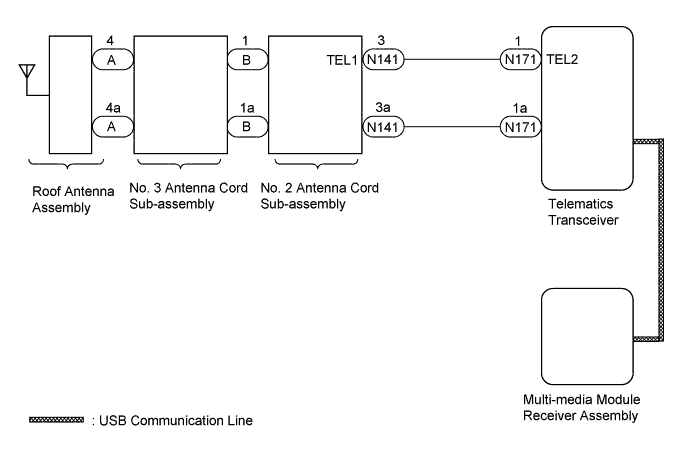
WIRING DIAGRAM
INSPECTION PROCEDURE
Note
-
Check for DTC B15DB. When DTC B15DB is output, perform troubleshooting for it first Click here.
-
Depending on the parts that are replaced during vehicle inspection or maintenance, performing initialization, registration or calibration may be needed. Refer to Precaution for G-BOOK Click here.
PROCEDURE
-
CHECK DTC OUTPUT
-
Clear the DTCs Click here.
-
Recheck for DTCs and check if the same DTC is output again.
OK B1573 or B15CB is not output.
NG 
INSPECT ROOF ANTENNA ASSEMBLY Click here
OK 
USE SIMULATION METHOD TO CHECK Click here
-
-
INSPECT ROOF ANTENNA ASSEMBLY
-
Remove the roof antenna assembly.
-
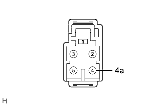
Measure the resistance according to the value(s) in the table below.
Standard Resistance Tester Connection Condition Specified Condition 4 - 4a Always 4 to 11 kΩ
NG 
REPLACE ROOF ANTENNA ASSEMBLY Click here
OK 
-
-
INSPECT NO. 3 ANTENNA CORD SUB-ASSEMBLY
-
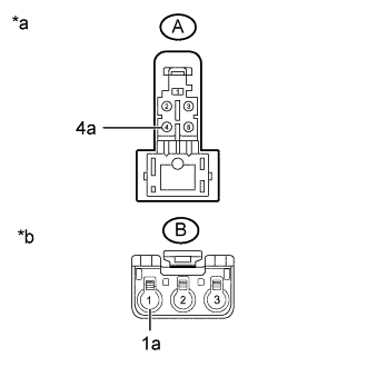
Text in Illustration *a Front view of wire harness connector
(to Roof Antenna Assembly)
*b Front view of wire harness connector
(to No. 2 Antenna Cord Sub-assembly)
Disconnect the No. 3 antenna cord sub-assembly from the roof antenna assembly connector.
-
Disconnect the No. 3 antenna cord sub-assembly from the No. 2 antenna cord sub-assembly.
-
Measure the resistance according to the value(s) in the table below.
Standard Resistance Tester Connection Condition Specified Condition A-4 - B-1 Always Below 1 Ω A-4a - B-1a Always Below 1 Ω A-4 - Body ground Always 10 kΩ or higher A-4a - Body ground Always 10 kΩ or higher
NG
REPLACE NO. 3 ANTENNA CORD SUB-ASSEMBLY Click here
OK
-
-
INSPECT NO. 2 ANTENNA CORD SUB-ASSEMBLY
-
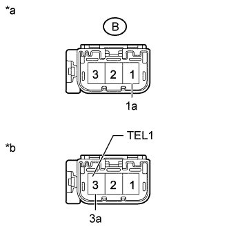
Text in Illustration *a Front view of wire harness connector
(to No. 3 Antenna Cord Sub-assembly)
*b Front view of wire harness connector
(to Instrument Panel Wire)
Disconnect the No. 2 antenna cord sub-assembly from the No. 3 antenna cord sub-assembly.
-
Disconnect the No. 2 antenna cord sub-assembly from the instrument panel wire.
-
Measure the resistance according to the value(s) in the table below.
Standard Resistance Tester Connection Condition Specified Condition B-1 - 3 (TEL1) Always Below 1 Ω B-1a - 3a Always Below 1 Ω B-1 - Body ground Always 10 kΩ or higher B-1a - Body ground Always 10 kΩ or higher
NG
REPLACE NO. 2 ANTENNA CORD SUB-ASSEMBLY Click here
OK
-
-
CHECK HARNESS AND CONNECTOR (NO. 2 ANTENNA CORD SUB-ASSEMBLY - TELEMATICS TRANSCEIVER)
-
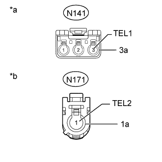
Text in Illustration *a Front view of wire harness connector
(to No. 2 Antenna Cord Sub-assembly)
*b Front view of wire harness connector
(to Telematics Transceiver)
Disconnect the N141 No. 2 antenna cord sub-assembly connector.
-
Disconnect the N171 telematics transceiver connector.
-
Measure the resistance according to the value(s) in the table below.
Standard Resistance Tester Connection Condition Specified Condition N141-3 (TEL1) - N171-1 (TEL2) Always Below 1 Ω N141-3a - N171-1a Always Below 1 Ω N141-3 (TEL1) - Body ground Always 10 kΩ or higher N141-3a - Body ground Always 10 kΩ or higher
NG
REPAIR OR REPLACE HARNESS OR CONNECTOR
OK
-
-
REPLACE TELEMATICS TRANSCEIVER
-
Replace the telematics transceiver with a new or known good one Click here.
NEXT
-
-
CHECK DTC OUTPUT
-
Clear the DTCs Click here.
-
Recheck for DTCs and check if the same DTC is output again.
OK B1573 or B15CB is not output.
NG
REPLACE MULTI-MEDIA MODULE RECEIVER ASSEMBLY Click here
OK
END (TELEMATICS TRANSCEIVER IS DEFECTIVE)
-