NAVIGATION SYSTEM, Diagnostic DTC:B1321, B1322, B1323, B1563

| DTC Code | DTC Name |
|---|---|
| B1321 | Lost Communication with EMV |
| B1322 | Lost Communication with Display |
| B1323 | Lost Communication with Haptic Device |
| B1563 | Haptic Device Disconnected |
DESCRIPTION
-
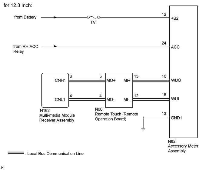
*1: for 12.3 Inch
-
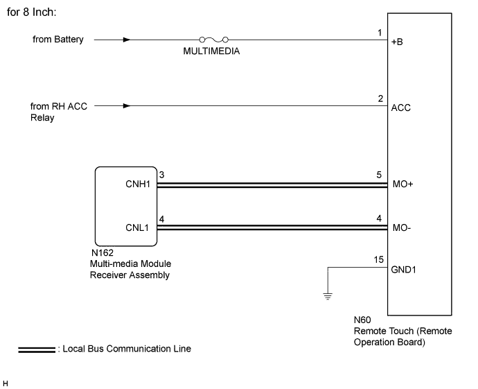
*2: for 8 Inch
These DTCs are stored when communication between the multi-media module receiver assembly and remote touch or accessory meter assembly is not possible.*1
These DTCs are stored when communication between the multi-media module receiver assembly and remote touch is not possible.*2
| DTC Code | DTC Detection Condition | Trouble Area |
|---|---|---|
| B1321 | The multi-media module receiver assembly cannot receive data from a device that is stored in memory as being connected to the multi-media module receiver assembly. |
|
| B1322*1 | The multi-media module receiver assembly cannot receive data from the accessory meter assembly. |
|
| B1323 | The remote touch cannot receive data from the multi-media module receiver assembly. |
|
| B1563 | The remote touch is/was not connected while the engine switch is/was on (ACC or IG). |
|
WIRING DIAGRAM
INSPECTION PROCEDURE
Note
-
Depending on the parts that are replaced during vehicle inspection or maintenance, performing initialization, registration or calibration may be needed. Refer to Precaution for Navigation System Click here.
-
Inspect the fuses for circuits related to this system before performing the following inspection procedure.
-
After turning the engine switch off, waiting time may be required before disconnecting the cable from the negative (-) battery terminal. Therefore, make sure to read the disconnecting the cable from the negative (-) battery terminal notices before proceeding with work Click here.
PROCEDURE
-
CHECK VEHICLE TYPE
-
Check the vehicle type.
Result Result Proceed to for 12.3 Inch A for 8 Inch B
B 
CHECK HARNESS AND CONNECTOR (MULTI-MEDIA MODULE RECEIVER ASSEMBLY - REMOTE TOUCH [REMOTE OPERATION BOARD]) Click here
A 
-
-
CHECK HARNESS AND CONNECTOR (ACCESSORY METER ASSEMBLY - REMOTE TOUCH [REMOTE OPERATION BOARD])
-
Disconnect the cable from the negative (-) battery terminal.
-
Disconnect the N62 accessory meter assembly connector.
-
Disconnect the N60 remote touch (remote operation board) connector.
-
Measure the resistance according to the value(s) in the table below.
Standard Resistance Tester Connection Condition Specified Condition N62-16 (WUO) - N60-13 (MI+) Always Below 1 Ω N62-15 (WUI) - N60-12 (MI-) Always Below 1 Ω N62-16 (WUO) - Body ground Always 10 kΩ or higher N62-15 (WUI) - Body ground Always 10 kΩ or higher N62-16 (WUO) - N62-15 (WUI) Always 10 kΩ or higher N62-16 (WUO) - N62-12 (+B2) Cable disconnected from negative (-) battery terminal 6 kΩ or higher N62-15 (WUI) - N62-12 (+B2) Cable disconnected from negative (-) battery terminal 6 kΩ or higher
NG 
REPAIR OR REPLACE HARNESS OR CONNECTOR
OK
-
-
CHECK HARNESS AND CONNECTOR (REMOTE TOUCH [REMOTE OPERATION BOARD] - MULTI-MEDIA MODULE RECEIVER ASSEMBLY)
-
Disconnect the cable from the negative (-) battery terminal.
-
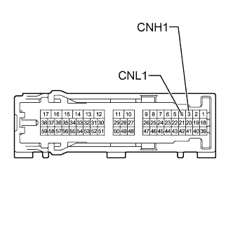
Disconnect the N162 multi-media module receiver assembly connector.
-
Disconnect the N60 remote touch (remote operation board) connector.
-
Disconnect the N62 accessory meter assembly connector.
-
Measure the resistance according to the value(s) in the table below.
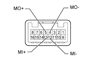
Standard Resistance Tester Connection Condition Specified Condition N162-3 (CNH1) - N60-5 (MO+) Always Below 1 Ω N162-4 (CNL1) - N60-4 (MO-) Always Below 1 Ω N162-3 (CNH1) - Body ground Always 10 kΩ or higher N162-4 (CNL1) - Body ground Always 10 kΩ or higher N162-3 (CNH1) - N162-4 (CNL1) Always 10 kΩ or higher N162-3 (CNH1) - N62-12 (+B2) Cable disconnected from negative (-) battery terminal 6 kΩ or higher N162-4 (CNL1) - N62-12 (+B2) Cable disconnected from negative (-) battery terminal 6 kΩ or higher
NG
REPAIR OR REPLACE HARNESS OR CONNECTOR
OK
-
-
CHECK HARNESS AND CONNECTOR (ACCESSORY METER ASSEMBLY POWER SOURCE)
-
Reconnect the cable from the negative (-) battery terminal.
-
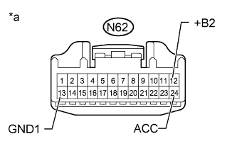
Text in Illustration *a Front view of wire harness connector
(to Accessory Meter Assembly)
Disconnect the N62 accessory meter assembly connector.
-
Measure the voltage according to the value(s) in the table below.
Standard Voltage Tester Connection Condition Specified Condition N62-12 (+B2) - Body ground Always 11 to 14 V N62-24 (ACC) - Body ground Engine switch on (ACC) 11 to 14 V -
Measure the resistance according to the value(s) in the table below.
Standard Resistance Tester Connection Condition Specified Condition N62-13 (GND1) - Body ground Always Below 1 Ω
NG
REPAIR OR REPLACE HARNESS OR CONNECTOR
OK
-
-
INSPECT MULTI-MEDIA MODULE RECEIVER ASSEMBLY
-
Remove the multi-media module receiver assembly Click here.
-
Measure the resistance according to the value(s) in the table below.
Standard Resistance Tester Connection Condition Specified Condition 3 (CNH1) - 4(CNL1) Always 108 to 132 Ω
NG
REPLACE MULTI-MEDIA MODULE RECEIVER ASSEMBLY Click here
OK
-
-
INSPECT REMOTE TOUCH (REMOTE OPERATION BOARD)
-
Remove the remote touch (remote operation board) Click here.
-
Measure the resistance according to the value(s) in the table below.
Standard Resistance Tester Connection Condition Specified Condition 13 (MI+) - 12 (MI-) Always 108 to 132 Ω 5 (MO+) - 4 (MO-) Always 108 to 132 Ω 13 (MI+) - 5 (MO+) Always Below 1 Ω 12 (MI-) - 4 (MO-) Always Below 1 Ω
NG
REPLACE REMOTE TOUCH (REMOTE OPERATION BOARD) Click here
OK
-
-
REMOTE TOUCH SELF CHECK (REMOTE TOUCH SWITCH KNOB FEEDBACK FORCE GENERATION CHECK)
-
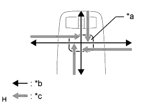
Text in Illustration *a Switch Knob *b Control Direction *c Feedback Force Check the remote touch switch knob feedback force.
-
Move the remote touch switch knob up, down, right and left to check that feedback force is generated.
OK Feedback force is generated. Tech Tips
When the engine switch is turned on (ACC), feedback force is generated. When the engine switch is turned off, feedback force is not generated, and the remote touch switch knob will move freely.
-
NG
REPLACE REMOTE TOUCH (REMOTE OPERATION BOARD) Click here
OK
-
-
REPLACE ACCESSORY METER ASSEMBLY
-
Replace the accessory meter assembly Click here.
NEXT
-
-
CLEAR DTC
-
Clear the DTCs Click here.
NEXT
-
-
CHECK DTC
-
Recheck for DTCs and check if the same DTC is output again Click here.
OK No DTCs are output.
NG
REPLACE MULTI-MEDIA MODULE RECEIVER ASSEMBLY Click here
OK 
END (ACCESSORY METER ASSEMBLY IS DEFECTIVE)
-
-
REPLACE MULTI-MEDIA MODULE RECEIVER ASSEMBLY
-
Replace the multi-media module receiver assembly Click here.
NEXT
-
-
CLEAR DTC
-
Clear the DTCs Click here.
NEXT
-
-
CHECK DTC
-
Recheck for DTCs and check if the same DTC is output again Click here.
OK No DTCs are output.
NG
REPLACE REMOTE TOUCH (REMOTE OPERATION BOARD) Click here
OK
-
-
CHECK REMOTE TOUCH (REMOTE OPERATION BOARD)
-
Turn the engine switch on (IG) and wait 30 seconds.
-
Check that the navigation system can be operated normally using the remote touch.
OK Navigation system returns to normal.
NG
REPLACE REMOTE TOUCH (REMOTE OPERATION BOARD) Click here
OK
END (MULTI-MEDIA MODULE RECEIVER ASSEMBLY IS DEFECTIVE)
-
-
CHECK HARNESS AND CONNECTOR (MULTI-MEDIA MODULE RECEIVER ASSEMBLY - REMOTE TOUCH [REMOTE OPERATION BOARD])
-
Disconnect the cable from the negative (-) battery terminal.
-
Disconnect the N60 remote touch (remote operation board) connector.
-
Disconnect the N162 multi-media module receiver assembly connector.
-
Measure the resistance according to the value(s) in the table below.
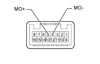
Standard Resistance Tester Connection Condition Specified Condition N60-5 (MO+) - N162-3 (CNH1) Always Below 1 Ω N60-4 (MO-) - N162-4 (CNL1) Always Below 1 Ω N60-5 (MO+) - Body ground Always 10 kΩ or higher N60-4 (MO-) - Body ground Always 10 kΩ or higher N60-5 (MO+) - N60-1 (+B) Cable disconnected from negative (-) battery terminal 6 kΩ or higher N60-4 (MO-) - N60-1 (+B) Cable disconnected from negative (-) battery terminal 6 kΩ or higher
NG
REPAIR OR REPLACE HARNESS OR CONNECTOR
OK
-
-
CHECK HARNESS AND CONNECTOR (REMOTE TOUCH [REMOTE OPERATION BOARD] POWER SOURCE)
-
Reconnect the cable from the negative (-) battery terminal.
-
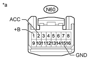
Text in Illustration *a Front view of wire harness connector
(to Remote Touch [Remote Operation Board])
Disconnect the remote touch (remote operation board) connector.
-
Measure the voltage according to the value(s) in the table below.
Standard Voltage Tester Connection Condition Specified Condition N60-1 (+B) - Body ground Always 11 to 14 V N60-2 (ACC) - Body ground Engine switch on (ACC) 11 to 14 V -
Measure the resistance according to the value(s) in the table below.
Standard Resistance Tester Connection Condition Specified Condition N60-15 (GND1) - Body ground Always Below 1 Ω
NG
REPAIR OR REPLACE HARNESS OR CONNECTOR
OK
-
-
INSPECT MULTI-MEDIA MODULE RECEIVER ASSEMBLY
-
Remove the multi-media module receiver assembly Click here.
-
Measure the resistance according to the value(s) in the table below.
Standard Resistance Tester Connection Condition Specified Condition 3 (CNH1) - 4(CNL1) Always 108 to 132 Ω
NG
REPLACE MULTI-MEDIA MODULE RECEIVER ASSEMBLY Click here
OK
-
-
INSPECT REMOTE TOUCH (REMOTE OPERATION BOARD)
-
Remove the remote touch (remote operation board) Click here.
-
Measure the resistance according to the value(s) in the table below.
Standard Resistance Tester Connection Condition Specified Condition 5 (MO+) - 4 (MO-) Always 108 to 132 Ω
NG
REPLACE REMOTE TOUCH (REMOTE OPERATION BOARD) Click here
OK
-
-
REMOTE TOUCH SELF CHECK (REMOTE TOUCH SWITCH KNOB FEEDBACK FORCE GENERATION CHECK)
-
Text in Illustration *a Switch Knob *b Control Direction *c Feedback Force Check the remote touch switch knob feedback force.
-
Move the remote touch switch knob up, down, right and left to check that feedback force is generated.
OK Feedback force is generated. Tech Tips
When the engine switch is turned on (ACC), feedback force is generated. When the engine switch is turned off, feedback force is not generated, and the remote touch switch knob will move freely.
-
NG
REPLACE REMOTE TOUCH (REMOTE OPERATION BOARD) Click here
OK
-
-
REPLACE MULTI-MEDIA MODULE RECEIVER ASSEMBLY
-
Replace the multi-media module receiver assembly Click here.
NEXT
-
-
CLEAR DTC
-
Clear the DTCs Click here.
NEXT
-
-
CHECK DTC
-
Recheck for DTCs and check if the same DTC is output again Click here.
OK No DTCs are output.
NG
REPLACE REMOTE TOUCH (REMOTE OPERATION BOARD) Click here
OK
-
-
CHECK REMOTE TOUCH (REMOTE OPERATION BOARD)
-
Turn the engine switch on (IG) and wait 30 seconds.
-
Check that the navigation system can be operated normally using the remote touch.
OK Navigation system returns to normal.
NG
REPLACE REMOTE TOUCH (REMOTE OPERATION BOARD) Click here
OK
END (MULTI-MEDIA MODULE RECEIVER ASSEMBLY IS DEFECTIVE)
-