NAVIGATION SYSTEM OPERATION CHECK

-
CHECK SYSTEM NORMAL CONDITION
-
If the symptom is applicable to any of the following, it is intended behavior, and not a malfunction.
Symptom Answer A longer route than expected is chosen. Depending on the road conditions, the multi-media module receiver assembly may determine that a longer route is quicker. Even when distance priority is high, the shortest route is not shown. Some routes may not be advised due to safety concerns. When the vehicle is put into motion immediately after the hybrid system starts, the navigation system deviates from the correct position. If the vehicle starts before the navigation system activates, the system may not react. When driving on certain types of roads, especially new roads, the vehicle position deviates from the correct position. When the vehicle is driving on new roads not available on the map data from the hard disk drive, the system attempts to match it to another nearby road, causing the position mark to deviate. -
The following symptoms are not malfunctions, but are caused by errors inherent in the GPS, gyro sensor, speed sensor or multi-media module receiver assembly.
-
The current position mark may be displayed on a nearby parallel road.
-
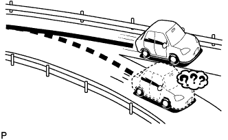
Immediately after a fork in the road, the current vehicle position mark may be displayed on the wrong road.
-
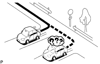
When the vehicle turns right or left at an intersection, the current vehicle position mark may be displayed on a nearby parallel road.
-
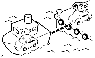
When the vehicle is carried, such as on a ferry, and the vehicle itself is not driving, the current vehicle position mark may be displayed in the position where the vehicle was until a measurement can be performed by the GPS.
-
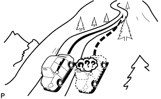
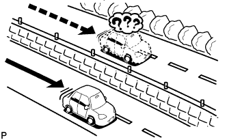
When the vehicle travels on a steep hill, the current vehicle position mark may deviate from the correct position.
-
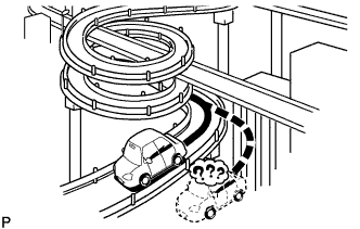
When the vehicle makes a continuous turn (e.g. 360, 720, 1080 degrees), the current vehicle position mark may deviate from the correct position.
-
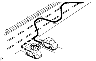
When the vehicle moves erratically, such as constant lane changes, the current vehicle position mark may deviate from the correct position.
-
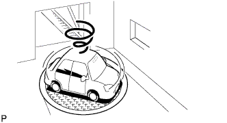
When the engine switch is turned on (ACC or IG) on a turntable before parking, the current vehicle position mark may not indicate the correct direction. The same will occur when the vehicle comes out of the parking garage.
-
When the vehicle travels on a snowy road or a mountain path with tire chains installed or using a spare tire, the current vehicle position mark may deviate from the correct position.
-
When the tires are changed, the current vehicle position mark may deviate from the correct position.
Tech Tips
-
A change in tire diameter may cause a speed sensor error.
-
Performing "tire change" in calibration mode will allow the system to correct the current vehicle position faster.
-
-
-
-
REMOTE TOUCH INITIAL CHECK
Note
-
Before performing the initial check, check that there are no foreign objects that will interfere with remote touch switch knob operation and that the knob is not stuck.
-
To avoid interruption of remote touch switch knob operation, do not touch the knob during the initial check.
Tech Tips
-
The remote touch performs initialization of its knob position at the time the vehicle is started and turned off.
-
When remote touch switch knob position initialization fails, DTC B1581 will be stored.
-
Move the remote touch switch knob to a position other than the center and turn the engine switch on (ACC).
-
Check that the remote touch switch knob moves automatically to the center of the movable area.
Tech Tips
-
Initialization of the remote touch switch knob position is complete when the knob moves to the center of the movable area.
-
If remote touch switch knob position initialization fails, remote touch switch knob operation and pointer movement on the screen will not match.
-
If the remote touch switch knob does not move to the center of the movable area within 10 seconds because of foreign objects or the knob being stuck, the remote touch will stop operating.
-
When the foreign object is removed or the remote touch switch knob is freed, and the knob position changes, the knob moves to the center of the movable area and completes its initialization.
-
The remote touch will repeatedly try to initialize itself until initialization has been completed, except when a built-in motor has a malfunction.
-
-
Move the remote touch switch knob to a position other than the center and turn the engine switch off.
-
Check that the remote touch switch knob automatically moves to the center of the movable area.
Tech Tips
-
Initialization of the remote touch switch knob position is complete when the knob moves to the center of the movable area.
-
If the remote touch switch knob does not move to the center of the movable area within 3 seconds because of foreign objects or the knob being stuck, the remote touch will stop operating. In this case, initialization of the knob position will not complete, but DTC B1581 will not be stored.
-
-
-
REMOTE TOUCH SELF CHECK
Note
-
Before performing the remote touch self check, check that there are no foreign objects that would interfere with remote touch switch knob operation and that the knob is not stuck.
-
To avoid interruption of remote touch switch knob operation, do not touch the knob unless instructed in the steps.
Tech Tips
The following checks can be done via the self check:
-
DTC check for the remote touch
-
Switch illumination check
-
Remote touch switch knob position recognition check
-
Switch operation check
-
Remote touch switch knob feedback force check
-
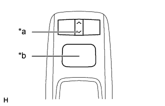
Text in Illustration *a Seesaw Switch "Down" *b Switch Knob Activate Self Check Mode
-
Turn the engine switch on (ACC) with the switch knob and down seesaw switch pressed to activate self check mode.
-
-
Switch Illumination Check and DTC Check
-
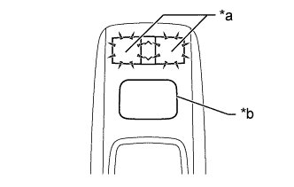
Text in Illustration *a Switch Illumination *b Switch Knob Check that the remote touch switch knob automatically moves to the center of the movable area and that the "MAP/VOICE" and "MENU" switch illumination blinks.
Tech Tips
-
If the remote touch switch knob does not automatically move to the center of the movable area, DTC B1581 is stored.
-
When DTCs are stored as a present DTC during self check, the "MAP/VOICE" and "MENU" switch illumination blinks at 0.5-second intervals. The illumination will continue to blink until the self check is completed.
-
The switch illumination stops blinking only when the factor that caused the remote touch switch knob malfunction (DTC B1581) disappears, allowing the knob to automatically move to the center of the movable area.
-
-
-
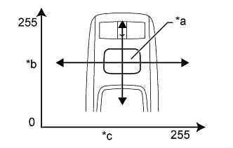
Text in Illustration *a Switch Knob *b Longitudinal Axis *c Lateral Axis Remote Touch Switch Knob Position Recognition Check
-
Move the remote touch switch knob up, down, right and left to check that the brightness of the "MAP/VOICE" and "MENU" switch illumination changes.
Tech Tips
-
If the brightness changes according to remote touch switch knob operation, the knob position is being recognized normally.
-
The brightness of the switch illumination changes between 0 and 100% according to the coordinates of the remote touch switch knob.
-
The coordinates of the remote touch switch knob change between 0 and 255 for both the lateral and longitudinal axes.
-
When the coordinates of both the lateral and longitudinal axes of the remote touch switch knob are 0, the brightness of the switch illumination becomes 0% (the lights will be off), and when the coordinates of both axes of the knob are 255, the brightness of the switch illumination becomes 100% (the switch lights will be on at full brightness).
-
-
-
Switch Operation Check
-
With the remote touch switch knob in the lower left position, check that pressing each switch on the remote touch turns on the "MAP/VOICE" and "MENU" switch illumination at 100% brightness.
Tech Tips
If the "MAP/VOICE" and "MENU" switch illumination turn on when a switch is pressed, the switch being pressed is operating normally.
-
-
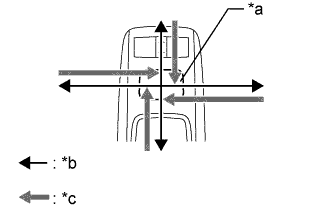
Text in Illustration *a Switch Knob *b Movement Direction *c Feedback Force Remote Touch Switch Knob Feedback Force Check
-
Move the remote touch switch knob up, down, right and left to check that feedback force is generated.
Tech Tips
The motors built into the remote touch generate feedback force according to the direction in which the remote touch switch knob is moved.
-
Move the pointer on the screen by operating the remote touch switch knob and check that the feedback force of the knob changes according to the screen being displayed and the pointer position.
Tech Tips
-
Refer to Remote Touch Outline for further information on remote touch switch knob feedback force generated according to the screen being displayed and the pointer position Click here.
-
When the feedback force of the remote touch switch knob changes according to the screen being displayed and the pointer position, it means that the remote touch is receiving feedback force request signals from the multi-media module receiver assembly.
-
When the remote touch cannot receive feedback force request signals from the multi-media module receiver assembly, the remote touch generates feedback force according to the default feedback force image recorded in the remote touch (remote operation board).
-
-
-
Finish Self Check Mode
-
Turn the engine switch off to finish self check mode.
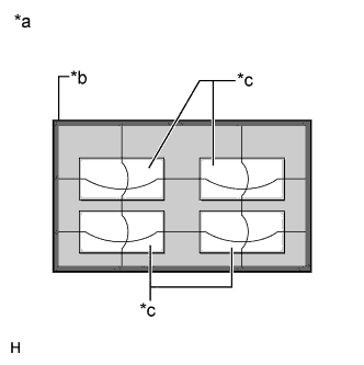
Text in Illustration *a Default Feedback Force Image *b Frame Area *c Icon Area
-
-
-
CHECK HARD DISK DRIVE
Tech Tips
-
Check the hard disk drive (HDD) built into the multi-media module receiver assembly.
-
Illustrations may differ from the actual vehicle screen depending on the device settings and options. Therefore, some detailed areas may not be shown exactly the same as on the actual vehicle screen.
-
Enter diagnostic mode Click here.
-
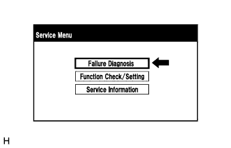
Select "Failure Diagnosis" from the "Service Menu" screen.
-
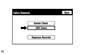
Select "HDD Check" from the "Failure Diagnosis" screen.
-
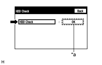
Text in Illustration *a Result HDD check
-
Select "HDD Check" to start the HDD check.
-
Check that the result is displayed when the HDD check is completed.
Screen Description Result Description Checking While the check is in progress OK Hard disk drive is normal NG Hard disk drive is malfunctioning Tech Tips
-
After selecting "HDD Check", it may take a while until the result is displayed.
-
If the cabin temperature is -20°C (-4°F) or lower, or 65°C (149°F) or higher, the HDD may not operate normally, and "NG" may be shown on the display. Make sure to perform the inspection with the cabin at an appropriate temperature.
-
If "NG" is displayed even when the cabin temperature is appropriate, replace the HDD with a new one.
-
-
-
-
CHECK PANEL & STEERING SWITCH
Tech Tips
-
The multi-media module receiver assembly panel switches, remote touch push switches and steering switch are checked in the following procedure.
-
Illustrations may differ from the actual vehicle screen depending on the device settings and options. Therefore, some detailed areas may not be shown exactly the same as on the actual vehicle screen.
-
Enter diagnostic mode Click here.
-
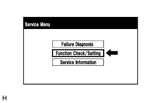
Select "Function Check/Setting" from the "Service Menu" screen.
-
for Korea
-
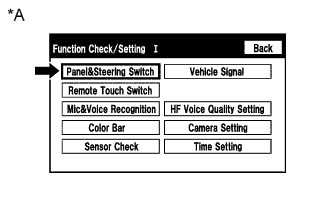
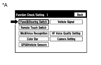
Text in Illustration *A for Korea Select "Panel&Steering Switch" from the "Function Check/Setting I" screen.
-
-
except Korea
-
Text in Illustration *A except Korea Select "Panel&Steering Switch" from the "Function Check/Setting I" screen.
-
-
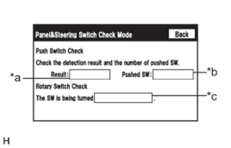
Panel & Steering Switch Check Mode
Screen Description Display Content *a: Switch condition "Pushed" is displayed when any switch is pushed *b: Number of switches pushed
-
Number of switches pushed at once is displayed
-
If more than 3 switches are pushed at once, "More than 3" is displayed
*c: Rotary switch direction Direction of rotary switch is displayed
-
Operate each switch and check that the switch conditions are correctly displayed.
Note
When the "SETUP" switch is pressed and held for 3 seconds or more, diagnostic mode will be canceled.
-
-
-
CHECK REMOTE TOUCH SWITCH
Tech Tips
-
The remote touch switch knob is checked in the following procedure.
-
Illustrations may differ from the actual vehicle screen depending on the device settings and options. Therefore, some detailed areas may not be shown exactly the same as on the actual vehicle screen.
-
Enter diagnostic mode Click here.
-
Select "Function Check/Setting" from the "Service Menu" screen.
-
for Korea
-
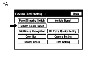
Text in Illustration *A for Korea Select "Remote Touch Switch" from the "Function Check/Setting I" screen.
-
-
except Korea
-
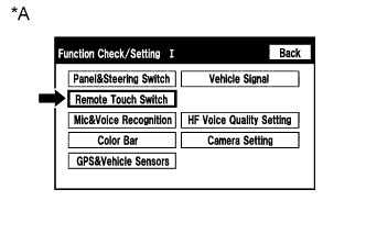
Text in Illustration *A except Korea Select "Remote Touch Switch" from the "Function Check/Setting I" screen.
-
-
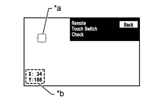
Remote Touch Switch Check for Main Screen
Screen Description Display Content *a: Cursor Displayed at the location where the pointer is located when the switch knob on the remote touch is pressed. *b: Coordinates
-
Displays the coordinates
-
"X" and "Y" indicate the lateral and longitudinal axes
-
Coordinates are displayed by numbers between 0 and 255 for each axis starting from the lower left of the screen
-
While "Remote Touch Switch Check" is displayed, move the pointer to any blank area of the screen using the remote touch switch knob, and press the switch knob.
Tech Tips
-
The cursor is displayed at the pointer position while the switch knob is pressed.
-
Once the cursor is displayed, the coordinates will be displayed.
-
Even though the pointer is moved, the cursor will remain at the position where the pointer was when the switch knob was pressed.
-
-
Move the pointer using the remote touch switch knob and press the switch knob again. When the location of the cursor is changed with the switch knob held, check that the coordinate values "X" and "Y" change between 0 and 255.
-
-
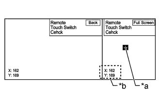
Remote Touch Switch Check for Side Screen
Screen Description Display Content *a: Cursor Displayed at the location where the pointer is located when the switch knob on the remote touch is pressed. *b: Coordinates
-
Displays the coordinates
-
"X" and "Y" indicate the lateral and longitudinal axes
-
Coordinates are displayed by numbers between 102 and 255 for horizontal axis and between 0 and 255 for vertical axis starting from the lower left of the screen
-
While "Remote Touch Switch Check" is displayed, move the pointer to any blank area of the screen using the remote touch switch knob, and press the switch knob.
Tech Tips
-
The cursor is displayed at the pointer position while the switch knob is pressed.
-
Once the cursor is displayed, the coordinates will be displayed.
-
Even though the pointer is moved, the cursor will remain at the position where the pointer was when the switch knob was pressed.
-
-
Move the pointer using the remote touch switch knob and press the switch knob again. When the location of the cursor is changed with the switch knob held, check that the coordinate values "X" change between 102 and 255 and "Y" change between 0 and 255.
-
-
Remote Touch Switch Check for Full Screen
-
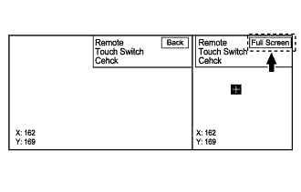
Select the "Full Screen" button on the side screen.
-
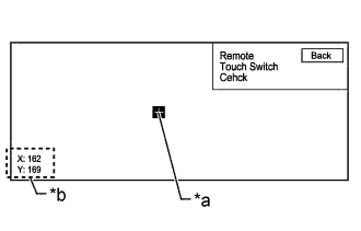
While "Remote Touch Switch Check" is displayed, move the pointer to any blank area of the screen using the remote touch switch knob, and press the switch knob.
Screen Description Display Content *a: Cursor Displayed at the location where the pointer is located when the switch knob on the remote touch is pressed. *b: Coordinates
-
Displays the coordinates
-
"X" and "Y" indicate the lateral and longitudinal axes
-
Coordinates are displayed by numbers between 0 and 255 for each axis starting from the lower left of the screen
Tech Tips
-
The cursor is displayed at the pointer position while the switch knob is pressed.
-
Once the cursor is displayed, the coordinates will be displayed.
-
Even though the pointer is moved, the cursor will remain at the position where the pointer was when the switch knob was pressed.
-
-
Move the pointer using the remote touch switch knob and press the switch knob again. When the location of the cursor is changed with the switch knob held, check that the coordinate values "X" change between 102 and 255 and "Y" change between 0 and 255.
-
-
-
CHECK MIC&VOICE RECOGNITION
Tech Tips
-
The microphone and microphone input level are checked in the following procedure.
-
Illustrations may differ from the actual vehicle screen depending on the device settings and options. Therefore, some detailed areas may not be shown exactly the same as on the actual vehicle screen.
-
Enter diagnostic mode Click here.
-
Select "Function Check/Setting" from the "Service Menu" screen.
-
for Korea
-
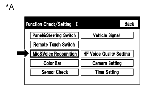
Text in Illustration *A for Korea Select "Mic&Voice Recognition" from the "Function Check/Setting I" screen.
-
-
except Korea
-
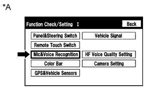
Text in Illustration *A except Korea Select "Mic&Voice Recognition" from the "Function Check/Setting I" screen.
-
-
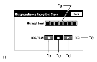
Microphone & Voice Recognition Check
Screen Description Display Content *a: Microphone input level meter Monitors the microphone input level every 0.1 seconds and displays the results in 8 different levels. *b: Recording switch Starts recording. *c: Stop switch Stops recording and playing. *d: Play switch Plays the recorded voice. *e: Recording indicator Comes on while recording.
-
When speaking into the microphone, check that the microphone input level meter changes according to the input level.
-
Select the recording switch and perform voice recording.
Tech Tips
Select the recording switch with the blower motor of the air conditioning system stopped. If an outlet of the air conditioning system is facing the microphone, noise may be recorded.
-
Check that the recording indicator remains on while recording and that the recording can be played normally.
Tech Tips
-
For details of this function, refer to Diagnosis Display Detailed Description in System Description Click here.
-
This function is controlled by the multi-media module receiver assembly (built-in navigation ECU).
-
-
-
-
CHECK COLOR BAR
Tech Tips
-
The display color on the screen is checked in the following procedure.
-
Illustrations may differ from the actual vehicle screen depending on the device settings and options. Therefore, some detailed areas may not be shown exactly the same as on the actual vehicle screen.
-
Enter diagnostic mode Click here.
-
Select "Function Check/Setting" from the "Service Menu" screen.
-
for Korea
-
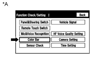
Text in Illustration *A for Korea Select "Color Bar" from the "Function Check/Setting I" screen.
-
-
except Korea
-
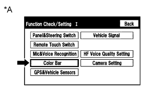
Text in Illustration *A except Korea Select "Color Bar" from the "Function Check/Setting I" screen.
-
-
Color Bar Check Mode for Main Screen
-
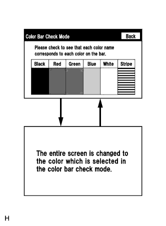
Select a color bar from the "Color Bar Check Mode" screen.
-
Check the display color.
Tech Tips
-
The entire screen turns to the color or stripe selected.
-
Touching the display will return to the "Color Bar Check Mode" screen.
-
-
-
Color Bar Check Mode for Full Screen
-
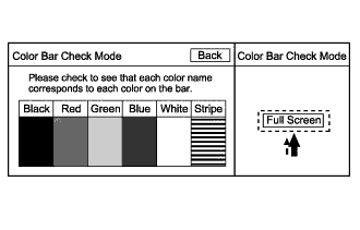
Select the "Full Screen" button on the side screen.
-
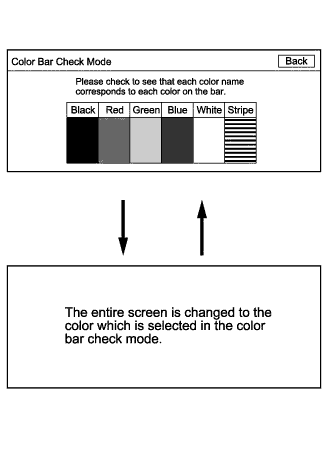
Select a color bar from the "Color Bar Check Mode" screen.
-
Check the display color.
Tech Tips
-
The entire screen turns to the color or stripe selected.
-
Touching the display will return to the "Color Bar Check Mode" screen.
-
-
-
-
CHECK SENSOR CHECK (for Korea)
Tech Tips
-
Vehicle signals and sensor signals are checked in the following procedure.
-
Illustrations may differ from the actual vehicle screen depending on the device settings and options. Therefore, some detailed areas may not be shown exactly the same as on the actual vehicle screen.
-
Enter diagnostic mode Click here.
-
Select "Function Check/Setting" from the "Service Menu" screen.
-
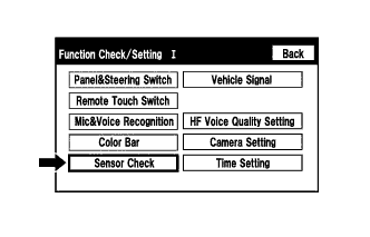
Select "Sensor Check" from the "Function Check/Setting I" screen.
-
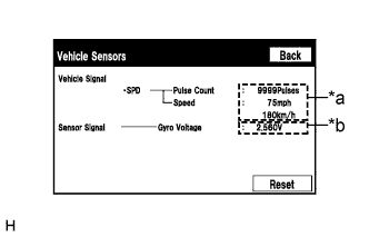
Vehicle Sensors
Screen Description Display Content *a: Vehicle signal Vehicle speed signal condition is displayed. *b: Sensor signal Gyro sensor output condition is displayed. Tech Tips
This screen is updated once per second.
-
Check all the signals and sensors when vehicle signal information is displayed.
-
-
-
CHECK GPS&VEHICLE SENSORS (except Korea)
Tech Tips
-
GPS information, vehicle signals and sensor signals are checked in the following procedure.
-
Illustrations may differ from the actual vehicle screen depending on the device settings and options. Therefore, some detailed areas may not be shown exactly the same as on the actual vehicle screen.
-
Enter diagnostic mode Click here.
-
Select "Function Check/Setting" from the "Service Menu" screen.
-
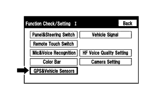
Select "GPS&Vehicle Sensors" from the "Function Check/Setting I" screen.
-
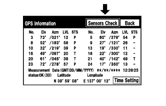
Select "Sensors Check" from the "GPS Information" screen.
-
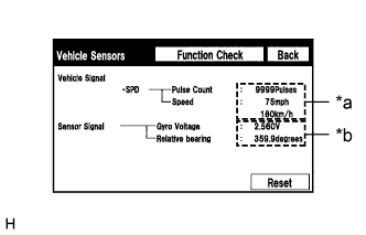
Vehicle Sensors
Screen Description Display Content *a: Vehicle signal Vehicle speed signal condition is displayed. *b: Sensor signal Gyro sensor output condition is displayed. Tech Tips
This screen is updated once per second.
-
Check all the signals and sensors when vehicle signal information is displayed.
-
-
-
CHECK VEHICLE SIGNALS
Tech Tips
-
Vehicle signals received by the multi-media module receiver assembly are checked in the following procedure.
-
Illustrations may differ from the actual vehicle screen depending on the device settings and options. Therefore, some detailed areas may not be shown exactly the same as on the actual vehicle screen.
-
Enter diagnostic mode Click here.
-
Select "Function Check/Setting" from the "Service Menu" screen.
-
for Korea
-
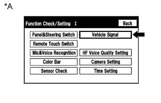
Text in Illustration *A for Korea Select "Vehicle Signal" from the "Function Check/Setting I" screen.
-
-
except Korea
-
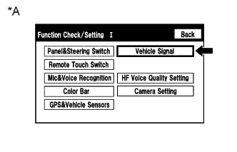
Text in Illustration *A except Korea Select "Vehicle Signal" from the "Function Check/Setting I" screen.
-
-
Vehicle Signal Check Mode
-
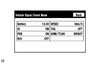
When the "Vehicle Signal Check Mode" screen is displayed, check all the vehicle signal conditions.
Screen Description Display Content Battery Battery voltage is displayed. IG Engine switch ON/OFF state is displayed. PKB Parking brake ON/OFF state is displayed. REV Reverse signal ON/OFF state is displayed. SPEED Vehicle speed is displayed in km/h. TAIL Tail signal (Light control switch) ON/OFF state is displayed. ADIM/TCAN Brightness state DIM (with) / BRIGHT (without) is displayed. Tech Tips
-
Only conditions having inputs are displayed.
-
This screen displays vehicle signals input to the multi-media module receiver assembly (built-in navigation ECU).
-
For details of this function, refer to Diagnosis Display Detailed Description in System Description Click here.
-
-
-
-
CHECK HANDS-FREE VOICE QUALITY AND VOLUME SETTING
Tech Tips
-
The hands-free volume of a "Bluetooth" compatible phone can be adjusted using the following procedure.
-
Illustrations may differ from the actual vehicle screen depending on the device settings and options. Therefore, some detailed areas may not be shown exactly the same as on the actual vehicle screen.
-
Enter diagnostic mode Click here.
-
Select "Function Check/Setting" from the "Service Menu" screen.
-
for Korea
-
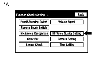
Text in Illustration *A for Korea Select "HF Voice Quality Setting" from the "Function Check/Setting I" screen.
-
-
except Korea
-
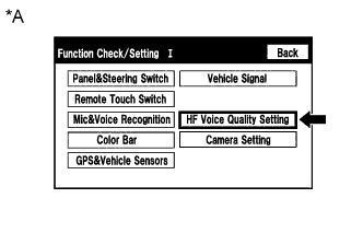
Text in Illustration *A except Korea Select "HF Voice Quality Setting" from the "Function Check/Setting I" screen.
-
-
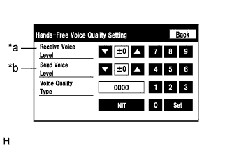
Hands-Free Voice Quality Setting (Receive/Send Voice Level adjustment)
Screen Description Display Content *a: Receive voice level adjustment Setting for the voice level received from "Bluetooth" compatible phones. *b: Send voice level adjustment Setting for the voice level sent from "Bluetooth" compatible phones. Note
Sound quality may deteriorate when the receive voice or send voice level is changed more than necessary. For this reason, check that the received voice or sent voice quality is still acceptable after changing this setting.
-
If the voice level is low, press the up button, and if the voice level is loud, press the down button.
Tech Tips
-
Settings will be applied when the up or down button is selected.
-
The received voice level adjustment ranges from -5 to +1.
-
The sent voice level adjustment ranges from -5 to +4.
-
The initial level is "0".
-
-
-

Screen Description *a Numeric keypad *b Setting button *c Reset button Hands-Free Voice Quality Setting (Voice Quality Type adjustment)
-
If necessary, refer to the table below to adjust the voice quality type with the numeric keypad.
-
When adjusting the settings, use the number pad on the screen to input the voice quality type according to the table.
Settings Parameter Target Phenomenon Voice Quality Type Positive Effect of Changing Voice Quality Negative Effect of Changing Voice Quality A
(Noise)
The change in background noise the other party hears becomes unpleasant. 1000 The change in background noise the other party hears is reduced. Background noise when not talking becomes large. B
(Noise)
The volume of the noise the other party hears temporarily becomes large. 2000 The temporary noise is reduced. The volume of voice may drop temporarily. C
(Echo)
The other party hears weak echoes. 0100 The amount of echo is reduced (low level). Sound quality of the other party deteriorates (low level). D
(Echo)
The other party hears strong echoes. 0200 The amount of echo is reduced (high level). Sound quality of the other party deteriorates (high level). E
(Quality)
The other party hears harsh noises. 0010 Sound the other party hears becomes soft. Sound the other party hears becomes muffled. F
(Quality)
You hear harsh noises. 0020 Sound you hear becomes soft. Sound you hear becomes muffled. Settings (When multiple phenomenon occurred) Parameter Target Phenomenon Voice Quality Type Positive Effect of Changing Voice Quality Negative Effect of Changing Voice Quality A+C The change in background noise the other party hears becomes unpleasant and the other party hears weak echoes. 1100
-
The change in background noise the other party hears is reduced.
-
The amount of echo is reduced (low level).
-
Background noise when not talking becomes large.
-
Sound quality of the other party deteriorates (low level).
A+D The change in background noise the other party hears becomes unpleasant and the other party hears strong echoes. 1200
-
The change in background noise the other party hears is reduced.
-
The amount of echo is reduced (high level).
-
Background noise when not talking becomes large.
-
Sound quality of the other party deteriorates (high level).
B+C The volume of the noise the other party hears temporarily becomes large and the other party hears weak echoes. 2100
-
The temporary noise is reduced.
-
The amount of echo is reduced (low level).
-
The volume of voice may drop temporarily.
-
Sound quality of the other party deteriorates (low level).
B+D The volume of the noise the other party hears temporarily becomes large and the other party hears strong echoes. 2200
-
The temporary noise is reduced.
-
The amount of echo is reduced (high level).
-
The volume of voice may drop temporarily.
-
Sound quality of the other party deteriorates (high level).
C+E The other party hears weak echoes and harsh noises. 0110
-
The amount of echo is reduced (low level).
-
Sound the other party hears becomes soft.
-
Sound quality of the other party deteriorates (low level).
-
Sound the other party hears becomes muffled.
C+F The other party hears weak echoes and you hear harsh noises. 0120
-
The amount of echo is reduced (low level).
-
Sound you hear becomes soft.
-
Sound quality of the other party deteriorates (low level).
-
Sound you hear becomes muffled.
Tech Tips
-
The default value is "0000".
-
Settings will be applied when the setting button is selected.
-
If voice quality type values that are not in the table are input, the setting will not be applied and a positive effect may not be gained.
-
If the quality of phone calls decreases due to the changed settings, return the settings to "0000" by pressing the "INIT" switch.
-
-
-
-
CHECK UNIT VERSION INFORMATION
Tech Tips
Illustrations may differ from the actual vehicle screen depending on the device settings and options. Therefore, some detailed areas may not be shown exactly the same as on the actual vehicle screen.
-
Enter diagnostic mode Click here.
-
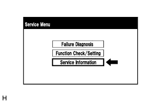
Select "Service Information" from the "Service Menu" screen.
-
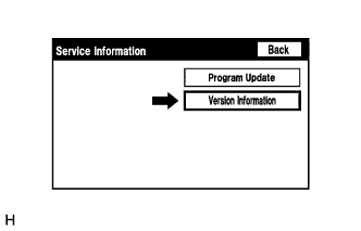
Select "Version Information" from the "Service Information" screen.
-
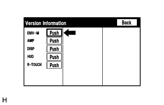
Press the "Push" switch.
-
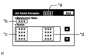
Unit Version Information
Screen Description Display Content *a: Device name Target device *b: Manufacturer name Manufacturer of the ECU (target device) *c: Component name Component name of the ECU (target device) *d: Version Version of the ECU (target device) Tech Tips
Depending on the manufacturer, some component names and versions will be displayed differently.
-
-
CHECK SOFTWARE ERROR HISTORY
Tech Tips
This function is used to check the cause when the multi-media module receiver assembly screen is blacked out.
-
Check software error history.
-
Connect the GTS to the DLC3.
-
Turn the engine switch on (IG).
-
Turn the GTS on.
-
Enter the following menus: Body Electrical / Navigation System/ Utility / Software Error History.
-
When an item is stored for Software Error History, record it before repairing the multi-media module receiver assembly.
Software Error History Screen Description Error Description Trigger Detail Software Reset Navi Microcomputer Hexadecimal Number Audio Microcomputer CAN Microcomputer No Video Signal Front Monitor Rear Monitor MOST Cold Restart Always Tech Tips
-
Software Error History can store up to 5 history data items. If a new software error occurs when 5 data items have already been stored, the oldest data is cleared and the new data is stored.
-
If an error that is unsupported by the GTS occurs, a "-" is displayed for the display items.
-
-
-
Clear software error history.
-
When DTCs are cleared using any of the following operations, Software Error History will be cleared as well Click here.
-
Cleared using the GTS.
-
Cleared using the system check mode screen.
-
Cleared using the unit check mode screen.
-
-
-
-
CHECK OPTICAL DISC ERROR HISTORY
Tech Tips
This function is used to check the cause of an optical disc error.
-
Check optical disc error history.
-
Connect the GTS to the DLC3.
-
Turn the engine switch on (IG).
-
Turn the GTS on.
-
Enter the following menus: Body Electrical / Navigation System / Utility / Optical Disc Error History.
-
When an item is stored for Optical Disc Error History, record it before proceeding with troubleshooting.
Optical Disc Error History Screen Description Display Content Error Type Displays the type of error. Device Displays the malfunctioning device. Date Displays the date and time that the malfunction occurred. "Error Type" Screen Description Error Type Detection Condition Action Read Error When a disc read error occurs. Proceed to next suspected area shown in Problem Symptoms Table Click here
Disc damaged/up side down/dirty When it is determined that any of the following is the cause of the disc read error:
-
The disc cannot be read.
-
The disc cannot be read because of dirt or scratches.
-
The disc cannot be read because it is inserted up side down.
Cannot determine disc type An unsuitable disc is inserted. DPS error When an error occurs while decoding MP3/WMA files. Some files are corrupt
-
When MP3/WMA files cannot be played back because they are unsupported.
-
Even though the file extensions are MP3 or WMA, files cannot be played back because the header information cannot be read.
Some files cannot be found
-
When a disc without music data is played back.
-
When there are no playable MP3/WMA files.
Copy protection violation When a file with copyright protection that cannot be played back is played back. "Device" Screen Description Device Component DVD-P Multi-media module receiver assembly CD-P Not available R-Seat DVD-P Not available Tech Tips
-
Optical Disc Error History can store up to 7 history data items. If a new optical disc error occurs when 7 data items have already been stored, the oldest data is cleared and the new data is stored.
-
If an error that is unsupported by the GTS occurs, a "-" or blank is displayed for the display items.
-
-
-
Clear optical disc error history.
-
When DTCs are cleared using any of the following operations, Optical Disc Error History will be cleared as well Click here.
-
Cleared using the GTS.
-
Cleared using the system check mode screen.
-
Cleared using the unit check mode screen.
-
-
-
-
MAP INFORMATION
Tech Tips
This function is used to check the map version of the navigation system and the end date of the map update service.
-
Check map information.
-
Connect the GTS to the DLC3.
-
Turn the engine switch on (IG).
-
Turn the GTS on.
-
Enter the following menus: Body Electrical / Navigation System / Utility / Map Information.
-
Check the map version and the end date of the map update service.
-
-