RADIO ANTENNA CORD INSTALLATION

-
INSTALL NO. 3 ANTENNA CORD SUB-ASSEMBLY
-
Attach the 5 clamps and install the No. 3 antenna cord sub-assembly.
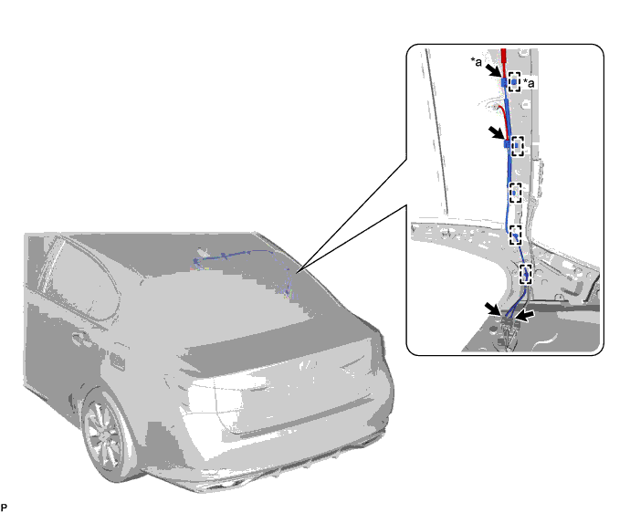
Text in Illustration *a w/ Digital Audio Broadcasting - - -
Connect the connectors.
-
-
INSTALL ROOF HEADLINING ASSEMBLY
-
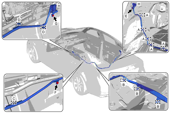
INSTALL NO. 2 ANTENNA CORD SUB-ASSEMBLY
-
Attach the 5 clips labeled A.
-
Attach the 3 clamps labeled B to the floor stud bolts.
-
Attach the clip labeled C.
-
Attach the 2 clips labeled D.
-
Install the bolt labeled E.
- Torque:
- 8.5 N*m { 87 kgf*cm, 75 in.*lbf }
-
Install the bolt labeled F.
- Torque:
- 8.5 N*m { 87 kgf*cm, 75 in.*lbf }
-
Install the bolt labeled G.
- Torque:
- 8.5 N*m { 87 kgf*cm, 75 in.*lbf }
-
Connect the connectors labeled H to install the No. 2 antenna cord sub-assembly.
-
-
INSTALL INNER ROOF SIDE GARNISH RH
Tech Tips
Use the same procedure described for the LH side.
-
INSTALL REAR SEAT SIDE GARNISH RH
Tech Tips
Use the same procedure described for the LH side.
-
INSTALL REAR DOOR SCUFF PLATE RH
Tech Tips
Use the same procedure described for the LH side.
-
INSTALL REAR SEAT ASSEMBLY
-
INSTALL FRONT SEAT ASSEMBLY RH
-
INSTALL CONSOLE BOX ASSEMBLY
-
INSTALL ANTENNA CORD SUB-ASSEMBLY
-
Attach the 2 clamps to install the antenna cord sub-assembly.
-
Connect the connector.
-
-
INSTALL MULTI-MEDIA MODULE RECEIVER ASSEMBLY
-
Connect the connectors.
-
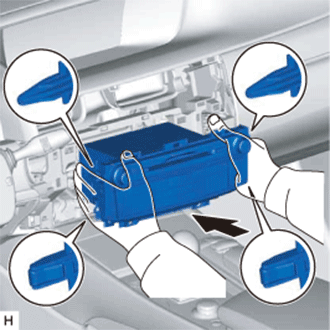
Insert the multi-media module receiver assembly with bracket.
Note
When inserting the multi-media module receiver, do not press the knobs on it.
-
Attach the 2 claws and 2 clips.
-
Install the multi-media module receiver assembly with bracket with the 2 screws.
-
-
INSTALL UPPER CONSOLE PANEL
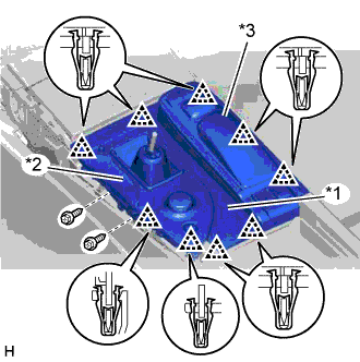
Text in Illustration *1 Upper Console Panel *2 Upper Rear Console Panel Sub-assembly *3 Remote Touch Assembly
-
Connect the connectors and attach the clamp.
-
Attach the 9 clips to install the upper console panel together with the upper rear console panel sub-assembly and remote touch assembly.
-
Install the 2 screws.
-
-
INSTALL SHIFT LEVER KNOB SUB-ASSEMBLY
-
Install the shift lever knob and twist it in the direction indicated by the arrow.
-
Attach the claw to install the shifting hole cover.
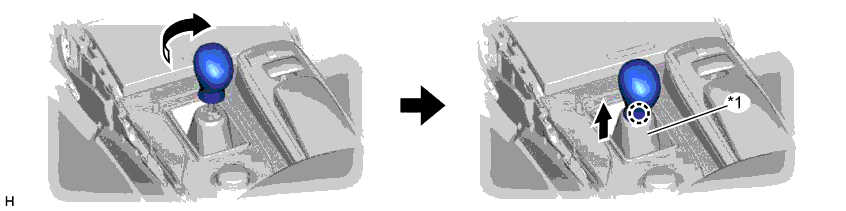
Text in Illustration *1 Shifting Hole Cover - -
-
-
INSTALL INSTRUMENT PANEL CUP HOLDER ASSEMBLY
-
Connect the connector.
-
Attach the 4 clips to install the instrument panel cup holder assembly.
-
-
INSTALL INSTRUMENT PANEL FINISH PANEL END LH
-
Attach the 5 clips and 2 guides to install the instrument panel finish panel end LH.
-
-
INSTALL INSTRUMENT PANEL FINISH PANEL END RH
-
Attach the 5 clips and 2 guides to install the instrument panel finish panel end RH.
-
-
INSTALL CENTER INSTRUMENT CLUSTER FINISH PANEL
-
Connect the connector.
-
Attach the 9 clips and guide to install the center instrument cluster finish panel.
-
-
CONNECT CABLE TO NEGATIVE BATTERY TERMINAL
Note
When disconnecting the cable, some systems need to be initialized after the cable is reconnected Click here.
-
INSPECT SRS WARNING LIGHT