RADIO ANTENNA CORD REMOVAL

-
PRECAUTION
Note
After turning the engine switch off, waiting time may be required before disconnecting the cable from the battery terminal. Therefore, make sure to read the disconnecting the cable from the battery terminal notice before proceeding with work Click here.
-
DISCONNECT CABLE FROM NEGATIVE BATTERY TERMINAL
Note
When disconnecting the cable, some systems need to be initialized after the cable is reconnected Click here.
-
REMOVE CENTER INSTRUMENT CLUSTER FINISH PANEL
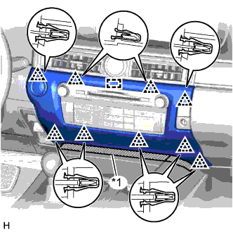
Text in Illustration *1 Protective Tape
-
Put protective tape around the center instrument cluster finish panel.
-
Detach the 9 clips and guide.
-
Disconnect the connector and remove the center instrument cluster finish panel.
-
-
REMOVE INSTRUMENT PANEL FINISH PANEL END RH
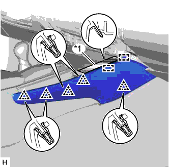
Text in Illustration *1 Protective Tape
-
Put protective tape around the instrument panel finish panel end RH.
-
Detach the 5 clips and 2 guides and remove the instrument panel finish panel end RH.
-
-
REMOVE INSTRUMENT PANEL FINISH PANEL END LH
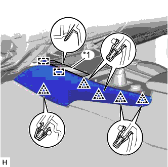
Text in Illustration *1 Protective Tape
-
Put protective tape around the instrument panel finish panel end LH.
-
Detach the 5 clips and 2 guides and remove the instrument panel finish panel end LH.
-
-
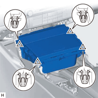
REMOVE INSTRUMENT PANEL CUP HOLDER ASSEMBLY
-
Detach the 4 clips.
-
Disconnect the connector and remove the instrument panel cup holder assembly.
-
-
REMOVE SHIFT LEVER KNOB SUB-ASSEMBLY
-
Detach the claw and slide the shifting hole cover downwards.
-
Twist the shift lever knob sub-assembly in the direction indicated by the arrow and remove it.
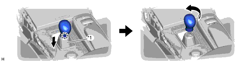
Text in Illustration *1 Shifting Hole Cover - -
-
-
REMOVE UPPER CONSOLE PANEL
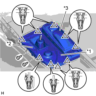
Text in Illustration *1 Upper Console Panel *2 Upper Rear Console Panel Sub-assembly *3 Remote Touch Assembly
-
Remove the 2 screws.
-
Detach the 9 clips.
-
Disconnect the connectors, detach the clamps, and remove the upper console panel together with the upper rear console panel sub-assembly and remote touch assembly.
-
-
REMOVE MULTI-MEDIA MODULE RECEIVER ASSEMBLY
-
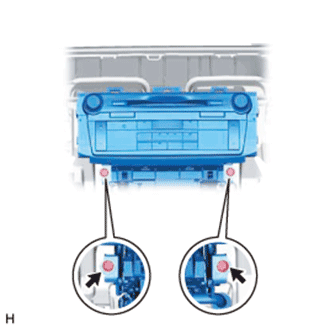
Remove the 2 screws.
-
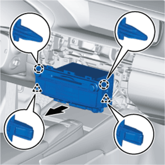
Detach the 2 claws and 2 clips.
-
Pull out the multi-media module receiver assembly with bracket.
-
Disconnect the connectors and remove the multi-media module receiver assembly with bracket.
-
-
REMOVE ANTENNA CORD SUB-ASSEMBLY
-
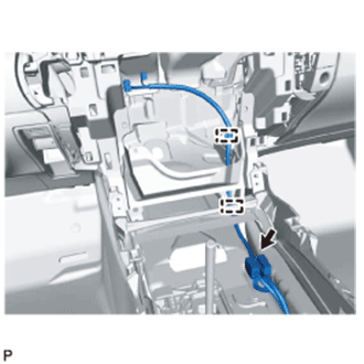
Disconnect the connector.
-
Detach the 2 clamps and remove the antenna cord sub-assembly.
-
-
REMOVE CONSOLE BOX ASSEMBLY
-
REMOVE FRONT SEAT ASSEMBLY RH
-
REMOVE REAR SEAT ASSEMBLY
-
REMOVE REAR DOOR SCUFF PLATE RH
Tech Tips
Use the same procedure described for the LH side.
-
REMOVE REAR SEAT SIDE GARNISH RH
Tech Tips
Use the same procedure described for the LH side.
-
REMOVE INNER ROOF SIDE GARNISH RH
Tech Tips
Use the same procedure described for the LH side.
-
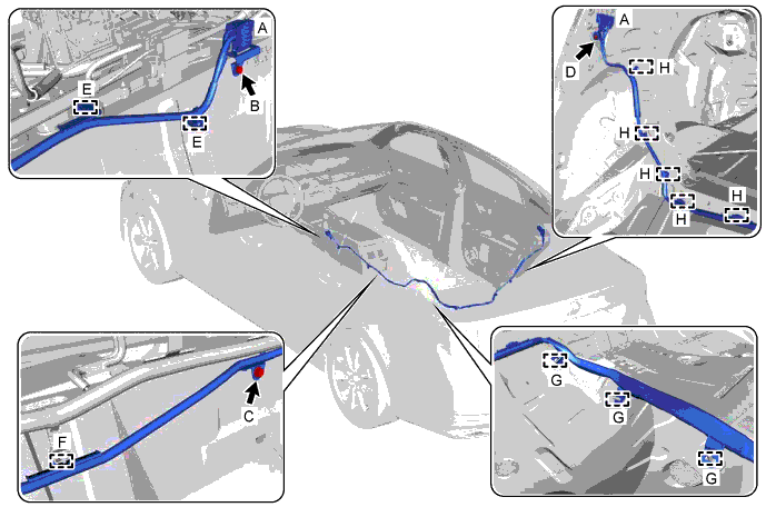
REMOVE NO. 2 ANTENNA CORD SUB-ASSEMBLY
-
Disconnect the connectors labeled A.
-
Remove the bolt labeled B.
-
Remove the bolt labeled C.
-
Remove the bolt labeled D.
-
Detach the 2 clips labeled E.
-
Detach the clamp labeled F.
-
Detach the 3 clamps labeled G from the floor stud bolts.
-
Detach the 5 clamps labeled H and remove the No. 2 antenna cord sub-assembly.
-
-
REMOVE ROOF HEADLINING ASSEMBLY
-
REMOVE NO. 3 ANTENNA CORD SUB-ASSEMBLY
-
Disconnect the connectors.
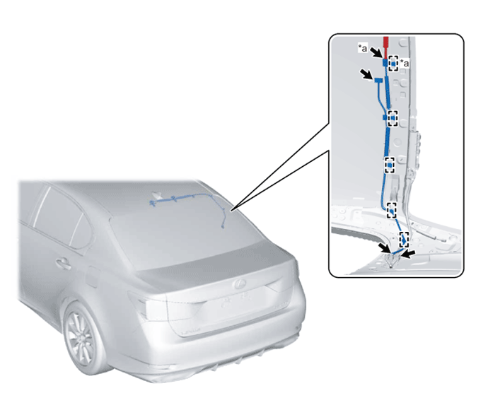
Text in Illustration *a w/ Digital Audio Broadcasting - - -
Detach the 5 clamps and remove the No. 3 antenna cord sub-assembly.
-