STEERING LINKAGE INSTALLATION

Tech Tips
-
Use the same procedure for RHD and LHD vehicles.
-
The procedure listed below is for LHD vehicles.
-
INSTALL POWER STEERING LINK ASSEMBLY (for 2WD)
-
Install the power steering link assembly with the 2 bolts, 2 washers, and 2 nuts.
- Torque:
- 118 N*m { 1199 kgf*cm, 87 ft.*lbf }
-
Connect the wire harness connectors to the power steering link assembly.
-
-
INSTALL POWER STEERING LINK ASSEMBLY (for AWD)
-
Install the power steering link assembly with the 2 bolts, 2 washers and 2 nuts.
- Torque:
- 102 N*m { 1038 kgf*cm, 75 ft.*lbf }
-
Connect the wire harness connectors to the power steering link assembly.
-
-
INSTALL ENGINE ASSEMBLY WITH TRANSMISSION (for AWD)
-
CONNECT TIE ROD ASSEMBLY LH (for 2WD)
-
Connect the tie rod assembly LH to the steering knuckle with the nut.
- Torque:
- 65 N*m { 663 kgf*cm, 48 ft.*lbf }
Note
If the holes for the clip are not aligned, tighten the nut up to an additional 60°.
-
Install a new clip.
-
-
CONNECT TIE ROD ASSEMBLY RH (for 2WD)
Tech Tips
Use the same procedure described for the LH side.
-
CONNECT TIE ROD ASSEMBLY LH (for AWD)
-
Connect the tie rod assembly LH to the steering knuckle with the nut.
- Torque:
- 65 N*m { 663 kgf*cm, 48 ft.*lbf }
-
Install a new clip.
-
-
CONNECT TIE ROD ASSEMBLY RH (for AWD)
Tech Tips
Use the same procedure described for the LH side.
-
INSTALL NO. 2 FRONT SUSPENSION MEMBER UPPER (for 2WD)
-
Install the 2 front No. 2 upper suspension members with the 6 bolts.
- Torque:
- 20 N*m { 204 kgf*cm, 15 ft.*lbf }
-
-
CONNECT STEERING SLIDING WITH SHAFT YOKE SUB-ASSEMBLY (for 2WD without VGRS)
-
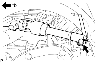
Text in Illustration *a Matchmark *b Vehicle Interior Align the matchmark on the steering sliding with shaft yoke with the matchmark on the power steering link and install the bolt.
- Torque:
- 35 N*m { 360 kgf*cm, 26 ft.*lbf }
-
Tighten the bolt closest to the vehicle interior.
- Torque:
- 35 N*m { 360 kgf*cm, 26 ft.*lbf }
-
-
CONNECT STEERING SLIDING WITH SHAFT YOKE SUB-ASSEMBLY (for 2WD with VGRS)
-
Align the matchmarks and correct the steering sliding with shaft yoke sub-assembly to the power steering gear assembly.
-
Install the 2 bolts.
- Torque:
- 35 N*m { 360 kgf*cm, 26 ft.*lbf }
-
-
CONNECT NO. 2 STEERING INTERMEDIATE SHAFT ASSEMBLY (for AWD)
-
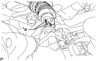
Text in Illustration *a Matchmark Align the matchmarks and connect the No. 2 steering intermediate shaft to the steering link.
-
Install the bolt.
- Torque:
- 35 N*m { 360 kgf*cm, 26 ft.*lbf }
-
-
INSTALL FRONT SUSPENSION MEMBER PROTECTOR LOWER (for 2WD)
-
Install the front lower suspension member protector with the 4 bolts.
- Torque:
- 5.5 N*m { 56 kgf*cm, 49 in.*lbf }
-
-
INSTALL NO. 2 ENGINE UNDER COVER (for 2WD)
-
Install the No. 2 engine under cover with the 4 screws and 2 grommets.
-
-
INSTALL FRONT SUSPENSION MEMBER BRACE (for 2WD)
-
Install the front suspension member brace with the clip and 4 bolts.
- Torque:
- 52 N*m { 530 kgf*cm, 38 ft.*lbf }
-
-
INSTALL REAR ENGINE UNDER COVER LH (for 2WD)
-
Install the rear engine under cover LH with the screw.
-
-
INSTALL REAR ENGINE UNDER COVER RH (for 2WD)
Tech Tips
Install the RH side following the same procedure as for the LH side.
-
INSTALL ENGINE UNDER COVER
-
Install the engine under cover with the 13 screws and 3 clips.
-
-
INSTALL FRONT WHEELS
- Torque:
- 103 N*m { 1050 kgf*cm, 76 ft.*lbf }
-
PLACE FRONT WHEELS FACING STRAIGHT AHEAD
-
CONNECT CABLE TO NEGATIVE BATTERY TERMINAL
-
Connect the cable to the negative battery terminal.
- Torque:
- 5.5 N*m { 56 kgf*cm, 49 in.*lbf }
Note
When disconnecting the cable, some systems need to be initialized after the cable is reconnected Click here.
-
-
ADJUST FRONT WHEEL ALIGNMENT
-
PREFORM POWER STEERING CALIBRATION
-
VARIABLE GEAR RATIO STEERING SYSTEM CALIBRATION (w/ VGRS)
-
PERFORM INITIALIZATION (w/ VGRS)