STEERING COLUMN ASSEMBLY REMOVAL

CAUTION:
Some of these service operations affect the SRS airbag system. Read the precautionary notices concerning the SRS airbag system before servicing the steering column Click here
Note
Ensure that the steering wheel is installed and aligned straight when inspecting the steering sensor.
Tech Tips
-
Use the same procedure for RHD and LHD vehicles.
-
The procedure listed below is for LHD vehicles.
-
PLACE FRONT WHEELS FACING STRAIGHT AHEAD
-
DISCONNECT CABLE FROM NEGATIVE BATTERY TERMINAL
-
Disable the auto tilt away function by changing the customize parameter Click here.
Note
Record the current customize parameter setting (whether the auto tilt away function is enabled or disabled) in order to restore the current setting after finishing the operation.
Tech Tips
Performing the above operation causes the auto tilt away function to be disabled when the engine switch is turned off.
-
Turn the engine switch on (IG). Operate the tilt and telescopic switch to fully extend and lower the steering column assembly.
-
Turn the engine switch off and disconnect the cable from the negative (-) battery terminal.
Note
When disconnecting the cable, some systems need to be initialized after the cable is reconnected Click here.
-
-
REMOVE STEERING WHEEL ASSEMBLY
-
REMOVE STEERING COLUMN COVER (w/o Driver Monitor Camera)
-
Remove the 3 screws.
-
Detach the 2 claws to remove the steering column lower cover.
Note
Do not damage the tilt and telescopic switch.
-
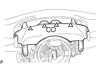
Detach the 4 clips.
-
Detach the 2 claws to remove the steering column upper cover.
-
-
REMOVE STEERING COLUMN COVER (w/ Driver Monitor Camera)
-
Remove the 3 screws.
-
Detach the 2 claws to remove the steering column lower cover.
Note
Do not damage the tilt and telescopic switch.
-
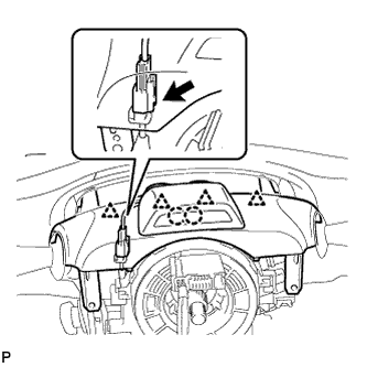
Detach the 4 clips.
-
Detach the 2 claws.
-
Disconnect the connectors and remove the steering column cover.
-
-
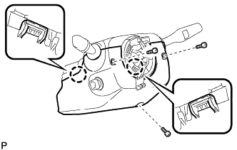
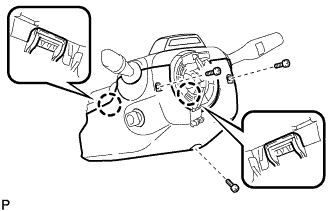
REMOVE TURN SIGNAL SWITCH ASSEMBLY WITH SPIRAL CABLE SUB-ASSEMBLY
-
Disconnect the connectors.
-
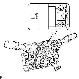
Detach the 3 claws with a screwdriver. Then remove the turn signal switch assembly with spiral cable sub-assembly from the steering column assembly.
-
-
REMOVE NO. 1 INSTRUMENT LOWER PANEL AIRBAG ASSEMBLY
-
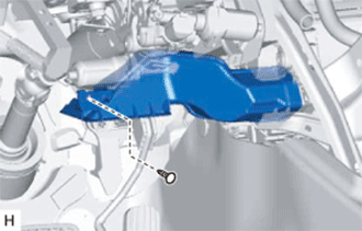
REMOVE NO. 1 AIR DUCT SUB-ASSEMBLY
-
Remove the clip and No. 1 air duct sub-assembly.
-
-
REMOVE STEERING SLIDING WITH SHAFT YOKE SUB-ASSEMBLY (for 2WD w/o VGRS)
-
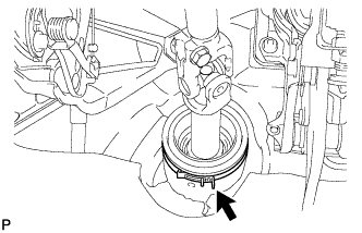
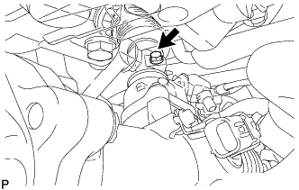
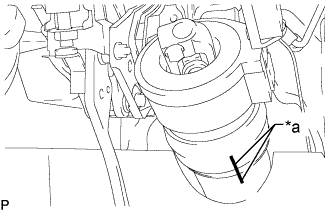
Remove the clamp from the steering column hole cover.
-
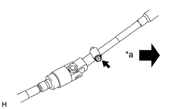
Text in Illustration *a Vehicle Interior Loosen the bolt of the steering sliding with shaft yoke closest to the vehicle interior.
-
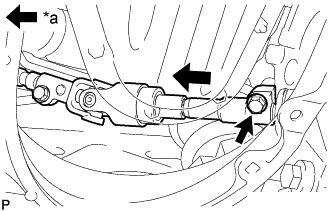
Text in Illustration *a Vehicle Interior Remove the bolt of the power steering link and the steering sliding with shaft yoke.
-
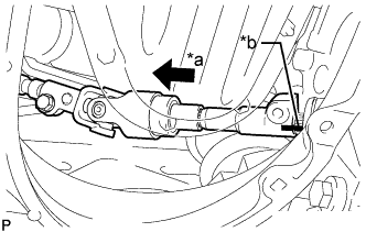
Text in Illustration *a Slide *b Matchmark Slide the steering sliding with shaft yoke and place matchmarks.
-
Disconnect the steering sliding with shaft yoke from the power steering link.
-
-
DISCONNECT NO. 2 STEERING INTERMEDIATE SHAFT ASSEMBLY (for AWD)
-
Remove the clamp from the steering column hole cover.
-
Remove the bolt from the steering intermediate shaft assembly.
-
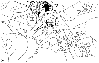
Text in Illustration *a Slide *b Matchmark Slide the No. 2 steering intermediate shaft assembly towards the vehicle interior and place matchmarks.
-
Disconnect the steering intermediate shaft from the power steering link.
-
-
DISCONNECT STEERING SLIDING WITH SHAFT YOKE SUB-ASSEMBLY (w/ VGRS)
-
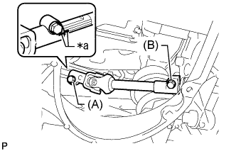
Text in Illustration *a Matchmark Loosen the bolt labeled A and remove the bolt labeled B, and then slide the steering sliding with shaft yoke sub-assembly.
Note
-
Do not remove the bolt labeled A.
-
Do not disconnect the steering sliding with shaft yoke sub-assembly from the power steering link assembly.
-
-
Put matchmark on the steering sliding with shaft yoke sub-assembly and steering actuator assembly.
-
Text in Illustration *a Matchmark Put matchmarks on the steering sliding with shaft yoke sub-assembly and power steering link assembly.
-
Disconnect the steering sliding with shaft yoke sub-assembly from the power steering link assembly.
-
Remove the bolt and steering sliding with shaft yoke sub-assembly from the steering actuator assembly.
-
-
REMOVE MAIN SHAFT LOWER DUST COVER (w/ VGRS)
-
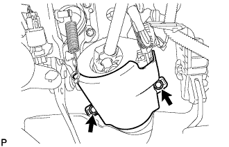
Remove the 2 bolts and dust cover.
-
-
REMOVE STEERING ACTUATOR ASSEMBLY (w/ VGRS)
-
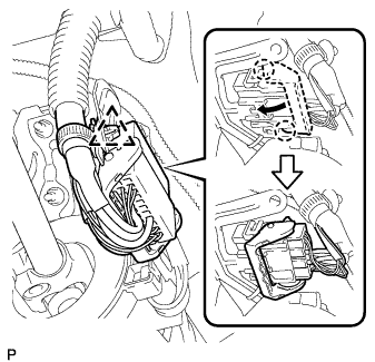
While pushing the claws on both sides of the connector, move the lock in the direction of the arrow.
-
Disconnect the connector from the steering actuator assembly.
-
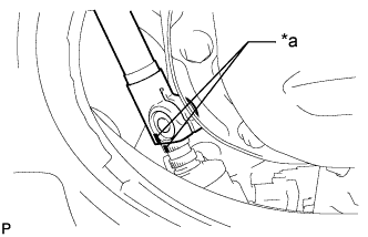
Remove the wire harness clamp from the steering column hole cover.
-
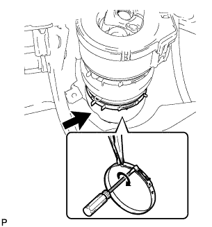
Pinch the clamp using needle-nose pliers, and then insert a precision screwdriver, turn it in the direction shown in the illustration and remove the No. 1 steering column hole cover clamp.
-
Text in Illustration *a Matchmark Put matchmarks on the steering actuator assembly and steering column hole shield.
-
Remove the steering actuator assembly.
-
-
REMOVE STEERING COLUMN ASSEMBLY (TILT STEERING GEAR ASSEMBLY WITH MOTOR)
-
Disconnect the connectors.
-
Remove the brake pedal return spring.
-
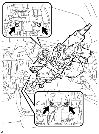
Remove the 4 nuts and steering column assembly.
-
-
DISCONNECT STEERING SLIDING WITH SHAFT YOKE SUB-ASSEMBLY
-
Put matchmarks on the steering sliding with shaft yoke and steering column assembly.
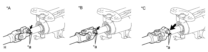
Text in Illustration *A for 2WD *B for AWD *C for 2WD (VGRS) *a Matchmark -
Remove the bolt and disconnect the steering sliding with shaft yoke sub-assembly.
-
-
REMOVE STEERING SLIDING WITH SHAFT YOKE SUB-ASSEMBLY (for 2WD)
-
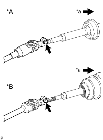
Text in Illustration *A w/o VGRS *B w/ VGRS *a Vehicle Interior Remove the bolt and steering sliding with shaft yoke sub-assembly.
-
-
REMOVE NO. 1 STEERING COLUMN HOLE COVER SUB-ASSEMBLY
-
Remove the 2 bolts, 2 nuts and steering column hole cover.
-