DYNAMIC REAR STEERING ACTUATOR INSTALLATION

-
INSTALL REAR STEERING LINK ASSEMBLY
-
Align the 2 guide pins with the suspension member and install the rear steering link assembly with the 4 bolts.
- Torque:
- 97 N*m { 989 kgf*cm, 72 ft.*lbf }
-
Install the nut and attach the clamp and grommet of the wire harness.
- Torque:
- 5.4 N*m { 55 kgf*cm, 48 in.*lbf }
-
Connect the 2 connectors to the rear steering control ECU.
-
Return the lock lever of each connector to its original position and attach the claw.
Note
Make sure the claw of the lock lever is securely attached.
-
-
INSTALL ECU BRACKET
-
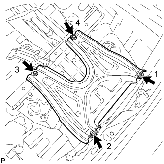
Install the ECU bracket with the 4 bolts.
Tech Tips
Temporarily install bolt 1, tighten the bolts in numerical order staring from bolt 2, and then tighten bolt 1.
- Torque:
- 8.5 N*m { 87 kgf*cm, 75 in.*lbf }
-
-
INSTALL SPARE WHEEL COVER TRAY ASSEMBLY
-
CONNECT REAR STEERING TIE ROD ASSEMBLY LH
-
Install a new nut to connect the tie rod assembly.
- Torque:
- 70 N*m { 714 kgf*cm, 52 ft.*lbf }
-
-
CONNECT REAR STEERING TIE ROD ASSEMBLY RH
Tech Tips
Use the same procedure as for the LH side.
-
INSTALL NO. 1 FLOOR UNDER COVER
-
Install the No. 1 floor under cover with the 4 clips and 6 nuts.
-
-
CONNECT CABLE TO NEGATIVE BATTERY TERMINAL
-
Connect the cable to the negative battery terminal.
- Torque:
- 5.5 N*m { 56 kgf*cm, 49 in.*lbf }
Note
When disconnecting the cable, some systems need to be initialized after the cable is reconnected Click here.
-
-
ADJUST WHEEL ALIGNMENT
-
PERFORM CALIBRATION
-
INSTALL REAR WHEELS
- Torque:
- 103 N*m { 1050 kgf*cm, 76 ft.*lbf }