POWER STEERING SYSTEM Power Steering Warning Light Circuit
DESCRIPTION
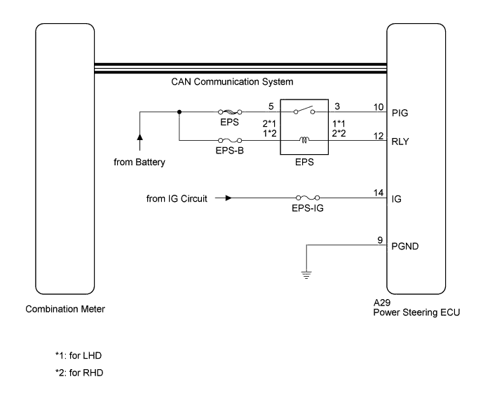
The power steering ECU is connected to the combination meter via CAN communication. If any of the following conditions are detected, the power steering warning light remains on.
-
The circuit that supplies power source voltage to the power steering ECU (terminal IG) is open.
-
The power supply voltage to the power steering ECU (terminals IG and PIG) drops.
WIRING DIAGRAM
INSPECTION PROCEDURE
Note
-
Inspect the fuses for circuits related to this system before performing the following inspection procedure.
-
If the power steering ECU assembly is replaced with a new one, perform assist map writing, clear the motor rotation angle sensor calibration value, initialize the motor rotation angle sensor value and calibrate the torque sensor zero point Click here.
PROCEDURE
-
CHECK HARNESS AND CONNECTOR
-
Start the engine.
-
Check the indication condition of the power steering warning light by wiggling the power steering ECU connector and wire harness up, down, right and left.
OK The power steering warning light indication condition does not change.
NG 
REPAIR OR REPLACE HARNESS OR CONNECTOR
OK 
-
-
CHECK CAN COMMUNICATION SYSTEM
-
Check for DTCs Click here.
Result Result Proceed to DTC is not output A DTC is output for LHD B for RHD C
B
GO TO CAN COMMUNICATION SYSTEM (HOW TO PROCEED WITH TROUBLESHOOTING) Click here
C
GO TO CAN COMMUNICATION SYSTEM (HOW TO PROCEED) Click here
A
-
-
CHECK TERMINAL VOLTAGE (IG)
-
Disconnect the power steering ECU connector.
-
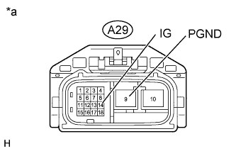
Text in Illustration *a Front view of wire harness connector
(to Power Steering ECU)
Measure the voltage according to the value(s) in the table below.
Standard Voltage Tester Connection Switch Condition Specified Condition A29-14 (IG) - Body ground Engine switch on (IG) 11 to 14 V -
Measure the resistance according to the value(s) in the table below.
Standard Resistance Tester Connection Condition Specified Condition A29-9 (PGND) - Body ground Always Below 1 Ω
NG
REPAIR OR REPLACE HARNESS OR CONNECTOR
OK
-
-
CHECK EPS RELAY (ELECTRIC POWER STEERING RELAY)
-
Remove the EPS relay (electric power steering relay) from the No. 1 engine room relay block.
-
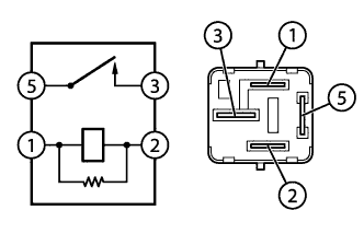
Measure the resistance according to the value(s) in the table below.
Standard Resistance Tester Connection Condition Specified Condition 1 - 2 20°C (68°F) 180 to 220 Ω 3 - 5 Battery voltage not applied to terminals 1 and 2 10 kΩ or higher Battery voltage applied to terminals 1 and 2 Below 1 Ω
NG
REPLACE EPS RELAY (ELECTRIC POWER STEERING RELAY)
OK
-
-
CHECK TERMINAL VOLTAGE (EPS RELAY)
-
Remove the EPS relay (electric power steering relay) from the No. 1 engine room relay block.
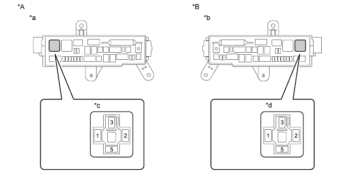
Text in Illustration *A for LHD *B for RHD *a Component without EPS relay (electric power steering relay)
(No. 1 Engine Room Relay Block)
*b Component without EPS relay (electric power steering relay)
(No. 1 Engine Room Relay Block)
*c Component without EPS relay (electric power steering relay)
EPS Relay (Electric Power Steering Relay) Connection Area
*d Component without EPS relay (electric power steering relay)
EPS Relay (Electric Power Steering Relay) Connection Area
-
Measure the voltage according to the value(s) in the table below.
Standard Voltage for LHD Tester Connection Condition Specified Condition 2 - Body ground Always 11 to 14 V 5 - Body ground Always 11 to 14 V for RHD Tester Connection Condition Specified Condition 1 - Body ground Always 11 to 14 V 5 - Body ground Always 11 to 14 V
NG
REPAIR OR REPLACE HARNESS OR CONNECTOR
OK
-
-
CHECK HARNESS AND CONNECTOR (NO. 1 ENGINE ROOM RELAY BLOCK - POWER STEERING ECU)
-
Remove the EPS relay (electric power steering relay) from the No. 1 engine room relay block.
-
Disconnect the A29 power steering ECU connector.
-
Measure the resistance according to the value(s) in the table below.
Standard Resistance for LHD Tester Connection Condition Specified Condition A29-12 (RLY) - 1 Always Below 1 Ω A29-10 (PIG) - 3 Always Below 1 Ω A29-12 (RLY) - A29-10 (PIG) Always 10 kΩ or higher A29-10 (PIG) - Body ground Always 10 kΩ or higher A29-12 (RLY) - Body ground Always 10 kΩ or higher for RHD Tester Connection Condition Specified Condition A29-12 (RLY) - 2 Always Below 1 Ω A29-10 (PIG) - 3 Always Below 1 Ω A29-12 (RLY) - A29-10 (PIG) Always 10 kΩ or higher A29-10 (PIG) - Body ground Always 10 kΩ or higher A29-12 (RLY) - Body ground Always 10 kΩ or higher
NG
REPAIR OR REPLACE HARNESS OR CONNECTOR
OK
-
-
REPLACE POWER STEERING ECU ASSEMBLY
-
Replace the power steering ECU assembly Click here.
-
Perform assist map writing, clear the motor rotation angle sensor calibration value, initialize the motor rotation angle sensor value and calibrate the torque sensor zero point Click here.
-
Check the illumination condition of the power steering warning light.
OK The power steering warning light illuminates with the engine switch on (IG) and turns off after the engine starts.
NG
REPLACE COMBINATION METER ASSEMBLY Click here
OK 
END
-