VARIABLE GEAR RATIO STEERING SYSTEM, Diagnostic DTC:C15A5/65

| DTC Code | DTC Name |
|---|---|
| C15A5/65 | Lock Mechanism Circuit |
DESCRIPTION
If the VGRS ECU (front steering control ECU) detects a malfunction in the lock mechanism, it turns the master warning light on, stores DTC C15A5/65 and stops VGRS operation.
| DTC Code | DTC Detection Condition | Trouble Area |
|---|---|---|
| C15A5/65 | Both conditions are met for approximately 0.025 seconds or more:
|
|
WIRING DIAGRAM
Refer to DTC C15A3/63 Click here.
INSPECTION PROCEDURE
Note
-
When replacing the VGRS ECU (front steering control ECU) or steering actuator assembly, perform actuator angle neutral position calibration and initialization after replacing parts Click here.
-
Since DTC C1B09/19 is stored in the DRS ECU (rear steering control ECU), after performing repairs on the VGRS system, clear the DTCs for the dynamic rear steering system.
PROCEDURE
-
CHECK HARNESS AND CONNECTOR (LV, LG TERMINAL)
-
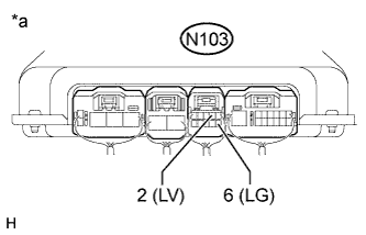
Text in Illustration *a Component with harness connected
(VGRS ECU [Front Steering Control ECU])
Turn the engine switch on (IG).
-
Measure the voltage according to the value(s) in the table below.
Tech Tips
With the connector connected to the VGRS ECU (front steering control ECU), measure the voltage from the rear of the connector.
Standard Voltage Tester Connection Switch Condition Specified Condition N103-2 (LV) - Body ground Engine switch on (IG) 11 to 14 V N103-6 (LG) - Body ground Engine switch on (IG) 11 to 14 V
NG 
INSPECT STEERING ACTUATOR ASSEMBLY Click here
OK 
-
-
READ VALUE USING GTS (LOCK SOLENOID VOLTAGE)
-
Turn the engine switch off.
-
Connect the GTS to the DLC3.
-
Start the engine.
-
Turn the GTS on.
-
Enter the following menus: Chassis / VGRS / Data List.
VGRS Tester Display Measurement Item/Range Normal Condition Diagnostic Note Lock Solenoid Voltage Lock solenoid voltage/
Min.: 0.00 V
Max.: 255.99 V
0 to 14 V - OK 0 to 14 V (while the engine is being started)
NG 
REPLACE FRONT STEERING CONTROL ECU Click here
OK 
USE SIMULATION METHOD TO CHECK Click here
-
-
INSPECT STEERING ACTUATOR ASSEMBLY
-
Turn the engine switch off.
-
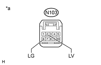
Text in Illustration *a Front view of wire harness connector
(to VGRS ECU [Front Steering Control ECU])
Disconnect the VGRS ECU (front steering control ECU) connector.
-
Measure the resistance according to the value(s) in the table below.
Tech Tips
Measure the resistance of the steering actuator assembly at the connector of the VGRS ECU (front steering control ECU).
Standard Resistance Tester Connection Condition Specified Condition N103-2 (LV) - N103-6 (LG) Always 10 to 30 Ω N103-2 (LV) - Body ground Always 100 kΩ or higher N103-6 (LG) - Body ground Always 100 kΩ or higher
NG
CHECK HARNESS AND CONNECTOR (FRONT STEERING CONTROL ECU - STEERING ACTUATOR ASSEMBLY) Click here
OK
REPLACE FRONT STEERING CONTROL ECU Click here
-
-
CHECK HARNESS AND CONNECTOR (FRONT STEERING CONTROL ECU - STEERING ACTUATOR ASSEMBLY)
-
Turn the engine switch off.
-
Disconnect the N103 VGRS ECU (front steering control ECU) connector.
-
Disconnect the N38 steering actuator assembly connector.
-
Measure the resistance according to the value(s) in the table below.
Standard Resistance Tester Connection Condition Specified Condition N103-2 (LV) - N38-7 (LV+) Always Below 1 Ω N103-6 (LG) - N38-16 (LG+) Always Below 1 Ω N103-2 (LV) - Body ground Always 100 kΩ or higher N103-6 (LG) - Body ground Always 100 kΩ or higher
NG
REPAIR OR REPLACE HARNESS OR CONNECTOR
OK
REPLACE STEERING ACTUATOR ASSEMBLY Click here
-