POWER STEERING SYSTEM, Diagnostic DTC:C1552/22, C1554/23

| DTC Code | DTC Name |
|---|---|
| C1552/22 | PIG Power Supply Voltage Malfunction |
| C1554/23 | Power Supply Relay Failure |
DESCRIPTION
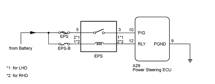
This circuit supplies power to drive the power steering motor.
| DTC Code | DTC Detection Condition | Trouble Area |
|---|---|---|
| C1552/22 | A PIG power supply voltage malfunction. |
|
| C1554/23 | A power supply relay malfunction. |
WIRING DIAGRAM
INSPECTION PROCEDURE
Note
-
Inspect the fuses for circuits related to this system before performing the following inspection procedure.
-
If the power steering ECU assembly is replaced with a new one, perform assist map writing, clear the motor rotation angle sensor calibration value, initialize the motor rotation angle sensor value and calibrate the torque sensor zero point Click here.
PROCEDURE
-
CHECK CONNECTORS
-
Check the connection of the power steering ECU connector.
-
Visually inspect the terminals of the power steering ECU connector.
Result Result Proceed to Normal A Connectors not properly connected B Power steering ECU connector terminals abnormal C
B 
CONNECT CONNECTORS CORRECTLY
C
REPLACE POWER STEERING ECU ASSEMBLY Click here
A 
-
-
CHECK HARNESS AND CONNECTOR (BATTERY - POWER STEERING ECU)
-
Disconnect the power steering ECU connector.
-
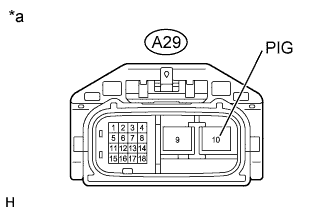
Text in Illustration *a Front view of wire harness connector
(to Power Steering ECU)
Measure the voltage according to the value(s) in the table below.
Standard Voltage Tester Connection Condition Specified Condition A29-10 (PIG) - Body ground Always Below 1 V
NG 
CHECK EPS RELAY (ELECTRIC POWER STEERING RELAY) Click here
OK
-
-
CHECK HARNESS AND CONNECTOR (BATTERY - POWER STEERING ECU)
-
Disconnect the power steering ECU connector.
-
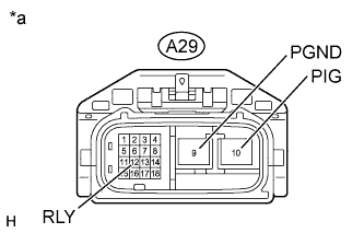
Text in Illustration *a Front view of wire harness connector
(to Power Steering ECU)
Measure the voltage according to the value(s) in the table below.
Standard Voltage Tester Connection Condition Specified Condition A29-10 (PIG) - Body ground Terminals A29-12 (RLY) and A29-9 (PGND) connected 11 to 14 V
NG
CHECK EPS RELAY (ELECTRIC POWER STEERING RELAY) Click here
OK 
REPLACE POWER STEERING ECU ASSEMBLY Click here
-
-
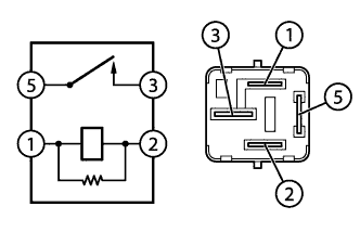
CHECK EPS RELAY (ELECTRIC POWER STEERING RELAY)
-
Remove the EPS relay (electric power steering relay) from the No. 1 engine room relay block.
-
Measure the resistance according to the value(s) in the table below.
Standard Resistance Tester Connection Condition Specified Condition 1 - 2 20°C (68°F) 180 to 220 Ω 3 - 5 Battery voltage not applied to terminals 1 and 2 10 kΩ or higher Battery voltage applied to terminals 1 and 2 Below 1 Ω
NG
REPLACE EPS RELAY (ELECTRIC POWER STEERING RELAY)
OK
-
-
CHECK TERMINAL VOLTAGE (EPS RELAY)
-
Remove the EPS relay (electric power steering relay) from the No. 1 engine room relay block.
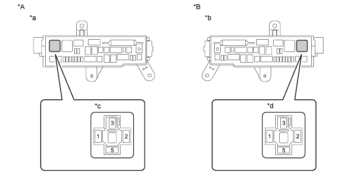
Text in Illustration *A for LHD *B for RHD *a Component without EPS relay (electric power steering relay)
(No. 1 Engine Room Relay Block)
*b Component without EPS relay (electric power steering relay)
(No. 1 Engine Room Relay Block)
*c Component without EPS relay (electric power steering relay)
EPS Relay (Electric Power Steering Relay) Connection Area
*d Component without EPS relay (electric power steering relay)
EPS Relay (Electric Power Steering Relay) Connection Area
-
Measure the voltage according to the value(s) in the table below.
Standard Voltage for LHD Tester Connection Condition Specified Condition 2 - Body ground Always 11 to 14 V 5 - Body ground Always 11 to 14 V for RHD Tester Connection Condition Specified Condition 1 - Body ground Always 11 to 14 V 5 - Body ground Always 11 to 14 V
NG
REPAIR OR REPLACE HARNESS OR CONNECTOR
OK
-
-
CHECK HARNESS AND CONNECTOR (NO. 1 ENGINE ROOM RELAY BLOCK - POWER STEERING ECU)
-
Remove the EPS relay (electric power steering relay) from the No. 1 engine room relay block.
-
Disconnect the A29 power steering ECU connector.
-
Measure the resistance according to the value(s) in the table below.
Standard Resistance for LHD Tester Connection Condition Specified Condition A29-12 (RLY) - 1 Always Below 1 Ω A29-10 (PIG) - 3 Always Below 1 Ω A29-12 (RLY) - A29-10 (PIG) Always 10 kΩ or higher A29-10 (PIG) - Body ground Always 10 kΩ or higher A29-12 (RLY) - Body ground Always 10 kΩ or higher for RHD Tester Connection Condition Specified Condition A29-12 (RLY) - 2 Always Below 1 Ω A29-10 (PIG) - 3 Always Below 1 Ω A29-12 (RLY) - A29-10 (PIG) Always 10 kΩ or higher A29-10 (PIG) - Body ground Always 10 kΩ or higher A29-12 (RLY) - Body ground Always 10 kΩ or higher
NG
REPAIR OR REPLACE HARNESS OR CONNECTOR
OK
REPLACE POWER STEERING ECU ASSEMBLY Click here
-