ELECTRIC PARKING BRAKE SYSTEM, Diagnostic DTC:C13A1/12

| DTC Code | DTC Name |
|---|---|
| C13A1/12 | Short in Power Supply Relay Circuit |
DESCRIPTION
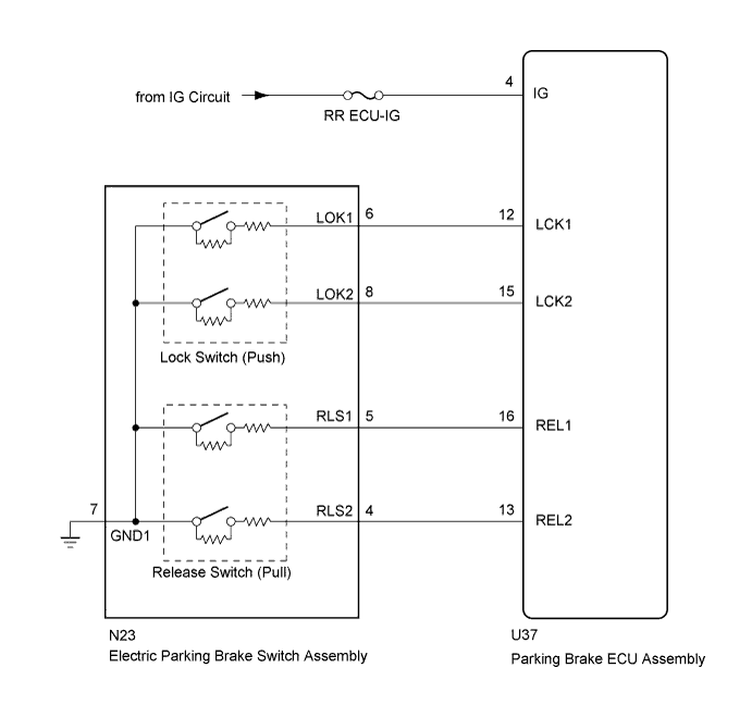
The parking brake ECU assembly performs the lock/release operation of the parking brake based on signals from the electric parking brake switch assembly, or instruction signals from other systems via CAN communication.
| DTC Code | Detection Condition | Trouble Area |
|---|---|---|
| C13A1/12 | Both of following conditions are met:
|
|
WIRING DIAGRAM
INSPECTION PROCEDURE
Note
-
If the parking brake ECU assembly or electric parking brake actuator is replaced, perform the "Reset Memory" and "Acquire Tension Sensor Zero Point" procedures Click here.
-
Before disconnecting connectors or fuses, turn the engine switch off and wait 20 seconds or more.
-
Inspect the fuses for circuits related to this system before performing the following inspection procedure.
PROCEDURE
-
CHECK HARNESS AND CONNECTOR (PARKING BRAKE ECU - IG POWER SOURCE CIRCUIT)
-
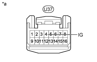
Text in Illustration *a Front view of wire harness connector
(to Parking Brake ECU Assembly)
Disconnect the parking brake ECU assembly connector.
-
Measure the voltage according to the value(s) in the table below.
Standard Voltage Tester Connection Switch Condition Specified Condition U37-4 (IG) - Body ground Engine switch off Below 2.5 V
NG 
REPAIR OR REPLACE HARNESS OR CONNECTOR
OK 
-
-
INSPECT ELECTRIC PARKING BRAKE SWITCH ASSEMBLY
-
Remove the electric parking brake switch assembly Click here.
-
Inspect the electric parking brake switch assembly Click here.
NG
REPLACE ELECTRIC PARKING BRAKE SWITCH ASSEMBLY Click here
OK
-
-
CHECK HARNESS AND CONNECTOR (PARKING BRAKE ECU - ELECTRIC PARKING BRAKE SWITCH ASSEMBLY)
-
Disconnect the N23 electric parking brake switch assembly connector.
-
Disconnect the parking brake ECU assembly connector.
-
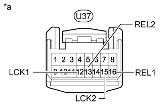
Text in Illustration *a Front view of wire harness connector
(to Parking Brake ECU Assembly)
Measure the resistance according to the value(s) in the table below.
Standard Resistance Tester Connection Condition Specified Condition U37-12 (LCK1) - Body ground Always 10 kΩ or higher U37-13 (REL2) - Body ground Always 10 kΩ or higher U37-15 (LCK2) - Body ground Always 10 kΩ or higher U37-16 (REL1) - Body ground Always 10 kΩ or higher
NG
REPAIR OR REPLACE HARNESS OR CONNECTOR
OK 
REPLACE PARKING BRAKE ECU ASSEMBLY Click here
-