VEHICLE STABILITY CONTROL SYSTEM VSC Buzzer Circuit
DESCRIPTION
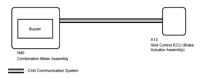
The skid control ECU (brake actuator assembly) is connected to the combination meter via CAN communication.
The combination meter has a built-in buzzer.
WIRING DIAGRAM
INSPECTION PROCEDURE
Note
When replacing the brake actuator assembly, perform zero point calibration and store system information Click here.
PROCEDURE
-
CHECK CAN COMMUNICATION SYSTEM
-
Check if a CAN communication system DTC is output (for LHD: Click here, for RHD: Click here.
Result Result Proceed to DTC is not output A DTC is output (for LHD) B DTC is output (for RHD) C
B 
GO TO CAN COMMUNICATION SYSTEM (HOW TO PROCEED WITH TROUBLESHOOTING) Click here
C
GO TO CAN COMMUNICATION SYSTEM (HOW TO PROCEED WITH TROUBLESHOOTING) Click here
A 
-
-
PERFORM ACTIVE TEST USING GTS (BUZZER)
-
Turn the engine switch off.
-
Connect the GTS to the DLC3.
-
Start the engine.
-
Turn the GTS on.
-
Enter the following menus: Chassis / ABS/VSC/TRC / Active Test.
ABS/VSC/TRC Tester Display Test Part Control Range Diagnostic Note Buzzer Meter Buzzer Buzzer ON/OFF The buzzer can be heard. -
When performing the Buzzer Active Test, check Buzzer in the Data List.
ABS/VSC/TRC Tester Display Measurement Item/Range Normal Condition Diagnostic Note Buzzer Buzzer/ ON or OFF ON: Buzzer on
OFF: Buzzer off
The combination meter has a built-in buzzer. Result Result Proceed to Data List Display Data List Display when Performing Active Test ON/OFF Operation ON Changes between ON and OFF A Does not change between ON and OFF B OFF Changes between ON and OFF A Does not change between ON and OFF B
B 
INSPECT COMBINATION METER ASSEMBLY Click here
A 
GO TO METER / GAUGE SYSTEM (HOW TO PROCEED WITH TROUBLESHOOTING) Click here
-
-
INSPECT COMBINATION METER ASSEMBLY
-
Inspect the combination meter Click here.
NG
REPLACE COMBINATION METER ASSEMBLY Click here
OK
REPLACE BRAKE ACTUATOR ASSEMBLY Click here
-