VEHICLE STABILITY CONTROL SYSTEM Skid Control Buzzer Circuit
DESCRIPTION
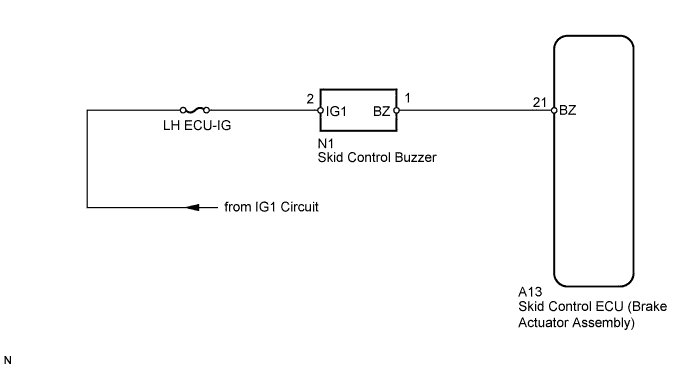
The skid control buzzer sounds upon receiving a signal from the skid control ECU (brake actuator assembly).
WIRING DIAGRAM
INSPECTION PROCEDURE
Note
-
Inspect the fuses for circuits related to this system before performing the following inspection procedure.
-
When replacing the brake actuator assembly, perform zero point calibration and store system information Click here.
PROCEDURE
-
PERFORM ACTIVE TEST USING GTS (DSS SIGNAL BUZZER)
-
Turn the engine switch off.
-
Connect the GTS to the DLC3.
-
Turn the engine switch on (IG).
-
Turn the GTS on.
-
Enter the following menus: Chassis / ABS/VSC/TRC / Active Test.
ABS/VSC/TRC Tester Display Test Part Control Range Diagnostic Note DSS Signal Buzzer Skid control buzzer Buzzer ON/OFF The buzzer can be heard. -
Check that the skid control buzzer sounds/stops when turning the skid control buzzer on/off by using the GTS.
Result Result Proceed to Buzzer does not sound or sounds constantly A Buzzer sounds/stops B
B 
CHECK FOR INTERMITTENT PROBLEMS Click here
A 
-
-
CHECK HARNESS AND CONNECTOR (IG1 TERMINAL)
-
Turn the engine switch off.
-
Disconnect the skid control buzzer connector.
-
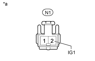
Text in Illustration *a Front view of wire harness connector
(to Skid Control Buzzer)
Measure the voltage according to the value(s) in the table below.
Standard Voltage Tester Connection Switch Condition Specified Condition N1-2 (IG1) - Body ground Engine switch on (IG) 11 to 14 V
NG
REPAIR OR REPLACE HARNESS OR CONNECTOR
OK
-
-
INSPECT SKID CONTROL BUZZER
-
Remove the skid control buzzer Click here.
-
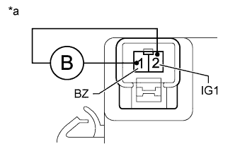
Text in Illustration *a Component without harness connected
(Skid Control Buzzer)
Apply battery voltage to the skid control buzzer, and check that the buzzer sounds.
OK Measurement Condition Specified Condition Battery positive (+) voltage - Terminal 2 (IG1) Skid control buzzer sounds Battery negative (-) voltage - Terminal 1 (BZ)
NG
REPLACE SKID CONTROL BUZZER ASSEMBLY Click here
OK
-
-
CHECK HARNESS AND CONNECTOR (SKID CONTROL BUZZER - SKID CONTROL ECU)
-
Turn the engine switch off.
-
Disconnect the A13 skid control ECU (brake actuator assembly) connector.
-
Disconnect the N1 skid control buzzer connector.
-
Measure the resistance according to the value(s) in the table below.
Standard Resistance Tester Connection Condition Specified Condition A13-21 (BZ) - N1-1 (BZ) Always Below 1 Ω A13-21 (BZ) - Body ground Always 10 kΩ or higher
NG
REPAIR OR REPLACE HARNESS OR CONNECTOR
OK 
REPLACE BRAKE ACTUATOR ASSEMBLY Click here
-