VEHICLE STABILITY CONTROL SYSTEM Slip Indicator Light Remains ON
DESCRIPTION
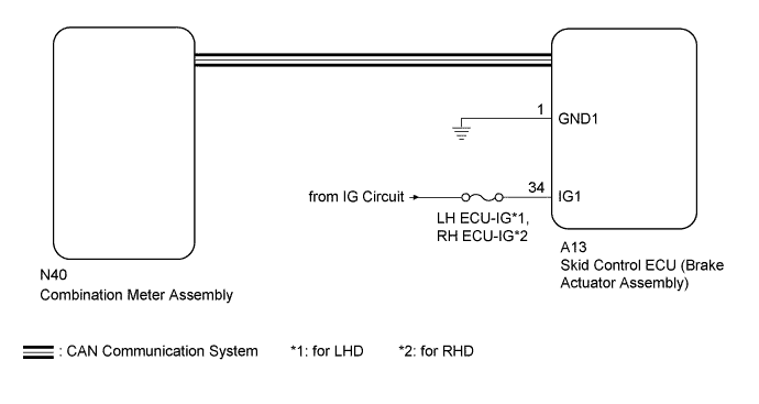
The skid control ECU (brake actuator assembly) is connected to the combination meter via CAN communication.
If the skid control ECU (brake actuator assembly) stores a DTC, the slip indicator light in the combination meter comes on.
The slip indicator light blinks during VSC and/or TRC operation.
When the system fails, the slip indicator light comes on to warn the driver Click here.
WIRING DIAGRAM
INSPECTION PROCEDURE
Note
-
When replacing the brake actuator assembly, perform zero point calibration and store system information Click here.
-
Inspect the fuses for circuits related to this system before performing the following inspection procedure.
PROCEDURE
-
CHECK CAN COMMUNICATION SYSTEM
-
Check if a CAN communication system DTC is output (for LHD: Click here, for RHD: Click here.
Result Result Proceed to DTC is not output A DTC is output (for LHD) B DTC is output (for RHD) C
B 
GO TO CAN COMMUNICATION SYSTEM (HOW TO PROCEED WITH TROUBLESHOOTING) Click here
C
GO TO CAN COMMUNICATION SYSTEM (HOW TO PROCEED WITH TROUBLESHOOTING) Click here
A 
-
-
CHECK IF SKID CONTROL ECU CONNECTOR IS SECURELY CONNECTED
-
Check if the skid control ECU (brake actuator assembly) connector is securely connected.
OK The connector is securely connected.
NG
CONNECT CONNECTOR TO ECU CORRECTLY
OK
-
-
CHECK HARNESS AND CONNECTOR (IG1 TERMINAL)
-
Disconnect the skid control ECU (brake actuator assembly) connector.
-
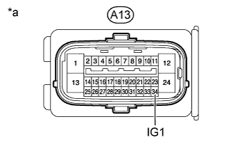
Text in Illustration *a Front view of wire harness connector
(to Skid Control ECU [Brake Actuator Assembly])
Measure the voltage according to the value(s) in the table below.
Standard Voltage Tester Connection Switch Condition Specified Condition A13-34 (IG1) - Body ground Engine switch on (IG) 11 to 14 V Result Result Proceed to OK A NG (for 2GR-FSE) B NG (for 4GR-FSE) C
NG
REPAIR OR REPLACE HARNESS OR CONNECTOR
OK
-
-
CHECK HARNESS AND CONNECTOR (GND1 TERMINAL)
-
Disconnect the skid control ECU (brake actuator assembly) connector.
-
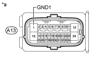
Text in Illustration *a Front view of wire harness connector
(to Skid Control ECU [Brake Actuator Assembly])
Measure the resistance according to the value(s) in the table below.
Standard Resistance Tester Connection Condition Specified Condition A13-1 (GND1) - Body ground Always Below 1 Ω
NG
REPAIR OR REPLACE HARNESS OR CONNECTOR
OK
-
-
PERFORM ACTIVE TEST USING GTS (SLIP INDICATOR LIGHT)
-
Turn the engine switch off.
-
Connect the GTS to the DLC3.
-
Start the engine.
-
Turn the GTS on.
-
Enter the following menus: Chassis / ABS/VSC/TRC / Active Test.
-
When performing the Slip Indicator Light Active Test, check Slip Indicator Light in the Data List.
Result Result Proceed to Data List Display Data List Display when Performing Active Test ON/OFF Operation ON Does not change between ON and OFF A Changes between ON and OFF B OFF Does not change between ON and OFF A Changes between ON and OFF B
B
GO TO METER / GAUGE SYSTEM (HOW TO PROCEED WITH TROUBLESHOOTING) Click here
A 
REPLACE BRAKE ACTUATOR ASSEMBLY Click here
-