POWER WINDOW CONTROL SYSTEM Driver Side Power Window does not Operate with Power Window Master Switch
DESCRIPTION
-
If the manual up/down function does not operate, there may be a malfunction in the multiplex network master switch, power window regulator motor, harness or connector.
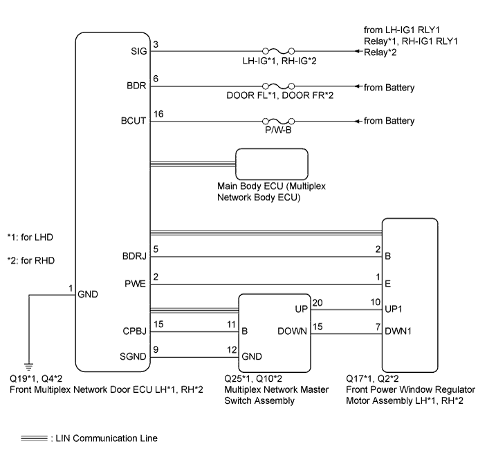
WIRING DIAGRAM
INSPECTION PROCEDURE
Note
-
Inspect the fuses and relays for circuits related to this system before performing the following inspection procedure.
-
If the power window regulator motor assembly has been replaced with a new one, initialize the power window control system Click here.
-
If the power window regulator motor assembly and door window regulator sub-assembly have been removed and installed, or if the power window regulator motor assembly was reused when a door glass or door glass run was replaced, initialize the power window control system Click here.
Tech Tips
Since the power window control system has functions that use LIN communication, first confirm that there is no malfunction in the communication system by inspecting the LIN communication functions in accordance with the "How to Proceed with Troubleshooting" procedures. Then, conduct the following inspection procedure.
PROCEDURE
-
READ VALUE USING GTS (D DOOR P/W SW)
-
Use the Data List to check if the front power window regulator motor is functioning properly Click here.
D-Door Motor Tester Display Measurement Item/Range Normal Condition Diagnostic Note D Door P/W Up SW Driver side power window manual up signal / ON or OFF ON: Driver side power window manual up switch operated
OFF: Driver side power window switch not operated
- D Door P/W Down SW Driver side power window manual down signal / ON or OFF ON: Driver side power window manual down switch operated
OFF: Driver side power window switch not operated
- OK On GTS screen, each item changes between ON and OFF according to above chart. Result Result Proceed to OK A NG (for LHD) B NG (for RHD) C
B 
CHECK HARNESS AND CONNECTOR (FRONT MULTIPLEX NETWORK DOOR ECU LH - BATTERY AND BODY GROUND) Click here
C
CHECK HARNESS AND CONNECTOR (FRONT MULTIPLEX NETWORK DOOR ECU RH - BATTERY AND BODY GROUND) Click here
A 
-
-
PERFORM ACTIVE TEST USING GTS (POWER WINDOW)
-
Select the Active Test, use the GTS to generate a control command, and then check that the power window regulator motor operates Click here.
D-Door Motor Tester Display Test Part Control Range Diagnostic Note Power Window Driver side power window OFF/UP/DOWN - OK The power window regulator motor operates normally. Result Result Proceed to OK A NG (for LHD) B NG (for RHD) C
B 
REPLACE FRONT POWER WINDOW REGULATOR MOTOR ASSEMBLY LH Click here
C
REPLACE FRONT POWER WINDOW REGULATOR MOTOR ASSEMBLY RH Click here
A 
REPLACE MULTIPLEX NETWORK MASTER SWITCH ASSEMBLY Click here
-
-
CHECK HARNESS AND CONNECTOR (FRONT MULTIPLEX NETWORK DOOR ECU LH - BATTERY AND BODY GROUND)
-
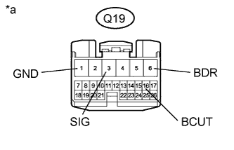
Text in Illustration *a Front view of wire harness connector
(to Front Multiplex Network Door ECU LH)
Disconnect the front multiplex network door ECU LH connector.
-
Measure the voltage and resistance according to the value(s) in the table below.
Standard Voltage Tester Connection Condition Specified Condition Q19-6 (BDR) - Q19-1 (GND) Always 11 to 14 V Q19-16 (BCUT) - Q19-1 (GND) Always 11 to 14 V Q19-3 (SIG) - Q19-1 (GND) Engine switch on (IG) 11 to 14 V Standard Resistance Tester Connection Condition Specified Condition Q19-1 (GND) - Body ground Always Below 1 Ω
NG
REPAIR OR REPLACE HARNESS OR CONNECTOR
OK
-
-
CHECK HARNESS AND CONNECTOR (MULTIPLEX NETWORK MASTER SWITCH ASSEMBLY - FRONT MULTIPLEX NETWORK DOOR ECU LH)
-
Disconnect the Q25 multiplex network master switch assembly connector.
-
Disconnect the Q19 front multiplex network door ECU LH connector.
-
Measure the resistance according to the value(s) in the table below.
Standard Resistance Tester Connection Condition Specified Condition Q25-11 (B) - Q19-15 (CPBJ) Always Below 1 Ω Q25-12 (GND) - Q19-9 (SGND) Always Below 1 Ω Q25-11 (B) - Body ground Always 10 kΩ or higher Q25-12 (GND) - Body ground Always 10 kΩ or higher
NG
REPAIR OR REPLACE HARNESS OR CONNECTOR
OK
-
-
CHECK HARNESS AND CONNECTOR (FRONT POWER WINDOW REGULATOR MOTOR ASSEMBLY LH - FRONT MULTIPLEX NETWORK DOOR ECU LH)
-
Disconnect the Q17 front power window regulator motor assembly LH connector.
-
Disconnect the Q19 front multiplex network door ECU LH connector.
-
Measure the resistance according to the value(s) in the table below.
Standard Resistance Tester Connection Condition Specified Condition Q17-2 (B) - Q19-5 (BDRJ) Always Below 1 Ω Q17-1 (E) - Q19-2 (PWE) Always Below 1 Ω Q17-2 (B) - Body ground Always 10 kΩ or higher Q17-1 (E) - Body ground Always 10 kΩ or higher
NG
REPAIR OR REPLACE HARNESS OR CONNECTOR
OK
-
-
CHECK FRONT MULTIPLEX NETWORK DOOR ECU LH
-
Measure the voltage according to the value(s) in the table below.

Text in Illustration *a Component with harness connected
(Front Multiplex Network Door ECU LH)
- - Standard Voltage Tester Connection Condition Specified Condition Q19-5 (BDRJ) - Body ground Always 11 to 14 V Q19-15 (CPBJ) - Body ground Always 11 to 14 V
NG
REPLACE FRONT MULTIPLEX NETWORK DOOR ECU LH Click here
OK
-
-
INSPECT FRONT DOOR MULTIPLEX NETWORK DOOR ECU LH
-
Remove the front multiplex network door ECU LH Click here.

-
Measure the resistance according to the value(s) in the table below.
Standard Resistance Tester Connection Condition Specified Condition 2 (PWE) - 1 (GND) Always Below 1 Ω 9 (SGND) - 1 (GND) Always Below 1 Ω
NG
REPLACE FRONT MULTIPLEX NETWORK DOOR ECU LH Click here
OK
-
-
CHECK HARNESS AND CONNECTOR (MULTIPLEX NETWORK MASTER SWITCH ASSEMBLY - FRONT POWER WINDOW REGULATOR MOTOR ASSEMBLY LH)
-
Disconnect the Q25 multiplex network master switch assembly connector.
-
Disconnect the Q17 power window regulator motor assembly LH connector.
-
Measure the resistance according to the value(s) in the table below.
Standard Resistance Tester Connection Condition Specified Condition Q25-20 (UP) - Q17-10 (UP1) Always Below 1 Ω Q25-15 (DOWN) - Q17-7 (DWN1) Always Below 1 Ω Q25-20 (UP) - Body ground Always 10 kΩ or higher Q25-15 (DOWN) - Body ground Always 10 kΩ or higher
NG
REPAIR OR REPLACE HARNESS OR CONNECTOR
OK
-
-
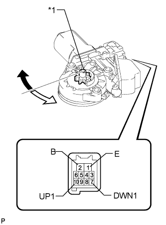
INSPECT FRONT POWER WINDOW REGULATOR MOTOR ASSEMBLY LH
Note
Do not apply positive (+) battery voltage to any terminals, except terminal 2 (B), to avoid damaging the pulse sensor inside the motor.
-
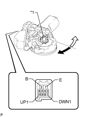
Text in Illustration *1 Motor Gear 
Clockwise 
Counterclockwise Remove the front power window regulator motor assembly LH Click here.
-
Apply positive (+) battery voltage to the connector terminal 2 (B).
-
Apply negative (-) battery voltage to the connector terminals 1 (E) and 7 (DWN1) / 10 (UP1).
-
Check that the motor gear rotates smoothly as follows.
OK Measurement Condition Specified Condition Battery positive (+) → 2 (B)
Battery negative (-): 1 (E) (3 seconds or more) → 1 (E) and 10 (UP1) (within 1 second) → 1 (E) (within 1 second) → 1 (E) and 10 (UP1)
Motor gear rotates clockwise (UP) Battery positive (+) → 2 (B)
Battery negative (-): 1 (E) (3 seconds or more) → 1 (E) and 7 (DWN1) (within 1 second) → 1 (E) (within 1 second) → 1 (E) and 7 (DWN1)
Motor gear rotates counterclockwise (DOWN) If the result is not as specified, replace the regulator motor assembly.
CAUTION:
Reset the power window regulator motor (initialize the pulse sensor) after installing the power window regulator motor and regulator assembly onto the door.
NG
REPLACE FRONT POWER WINDOW REGULATOR MOTOR ASSEMBLY LH Click here
OK
REPLACE MULTIPLEX NETWORK MASTER SWITCH ASSEMBLY Click here
-
-
CHECK HARNESS AND CONNECTOR (FRONT MULTIPLEX NETWORK DOOR ECU RH - BATTERY AND BODY GROUND)
-

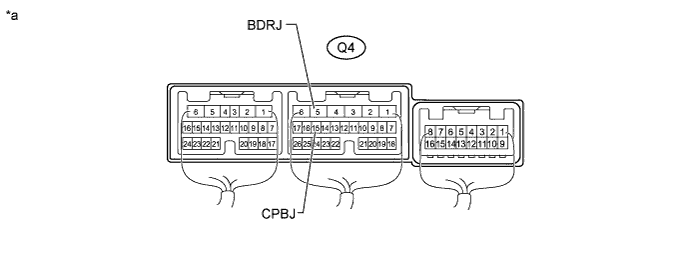
Text in Illustration *a Front view of wire harness connector
(to Front Multiplex Network Door ECU RH)
Disconnect the front multiplex network door ECU RH connector.
-
Measure the voltage and resistance according to the value(s) in the table below.
Standard Voltage Tester Connection Condition Specified Condition Q4-6 (BDR) - Q4-1 (GND) Always 11 to 14 V Q4-16 (BCUT) - Q4-1 (GND) Always 11 to 14 V Q4-3 (SIG) - Q4-1 (GND) Engine switch on (IG) 11 to 14 V Standard Resistance Tester Connection Condition Specified Condition Q4-1 (GND) - Body ground Always Below 1 Ω
NG
REPAIR OR REPLACE HARNESS OR CONNECTOR
OK
-
-
CHECK HARNESS AND CONNECTOR (MULTIPLEX NETWORK MASTER SWITCH ASSEMBLY - FRONT MULTIPLEX NETWORK DOOR ECU RH)
-
Disconnect the Q10 multiplex network master switch assembly connector.
-
Disconnect the Q2 front multiplex network door ECU RH connector.
-
Measure the resistance according to the value(s) in the table below.
Standard Resistance Tester Connection Condition Specified Condition Q10-11 (B) - Q2-15 (CPBJ) Always Below 1 Ω Q10-12 (GND) - Q2-9 (SGND) Always Below 1 Ω Q10-11 (B) - Body ground Always 10 kΩ or higher Q10-12 (GND) - Body ground Always 10 kΩ or higher
NG
REPAIR OR REPLACE HARNESS OR CONNECTOR
OK
-
-
CHECK HARNESS AND CONNECTOR (FRONT POWER WINDOW REGULATOR MOTOR ASSEMBLY RH - FRONT MULTIPLEX NETWORK DOOR ECU RH)
-
Disconnect the Q2 front power window regulator motor assembly RH connector.
-
Disconnect the Q4 front multiplex network door ECU RH connector.
-
Measure the resistance according to the value(s) in the table below.
Standard Resistance Tester Connection Condition Specified Condition Q2-2 (B) - Q4-5 (BDRJ) Always Below 1 Ω Q2-1 (E) - Q4-2 (PWE) Always Below 1 Ω Q2-2 (B) - Body ground Always 10 kΩ or higher Q2-1 (E) - Body ground Always 10 kΩ or higher
NG
REPAIR OR REPLACE HARNESS OR CONNECTOR
OK
-
-
CHECK FRONT MULTIPLEX NETWORK DOOR ECU RH
-
Measure the voltage according to the value(s) in the table below.
Text in Illustration *a Component with harness connected
(Front Multiplex Network Door ECU RH)
- - Standard Voltage Tester Connection Condition Specified Condition Q4-5 (BDRJ) - Body ground Always 11 to 14 V Q4-15 (CPBJ) - Body ground Always 11 to 14 V
NG
REPLACE FRONT MULTIPLEX NETWORK DOOR ECU RH Click here
OK
-
-
INSPECT FRONT MULTIPLEX NETWORK DOOR ECU RH
-
Remove the front multiplex network door ECU RH Click here.
-
Measure the resistance according to the value(s) in the table below.
Standard Resistance Tester Connection Condition Specified Condition 2 (PWE) - 1 (GND) Always Below 1 Ω 9 (SGND) - 1 (GND) Always Below 1 Ω
NG
REPLACE FRONT MULTIPLEX NETWORK DOOR ECU RH Click here
OK
-
-
CHECK HARNESS AND CONNECTOR (MULTIPLEX NETWORK MASTER SWITCH ASSEMBLY - FRONT POWER WINDOW REGULATOR MOTOR ASSEMBLY RH)
-
Disconnect the Q10 multiplex network master switch assembly connector.
-
Disconnect the Q2 power window regulator motor assembly RH connector.
-
Measure the resistance according to the value(s) in the table below.
Standard Resistance Tester Connection Condition Specified Condition Q10-20 (UP) - Q2-10 (UP1) Always Below 1 Ω Q10-15 (DOWN) - Q2-7 (DWN1) Always Below 1 Ω Q10-20 (UP) - Body ground Always 10 kΩ or higher Q10-15 (DOWN) - Body ground Always 10 kΩ or higher
NG
REPAIR OR REPLACE HARNESS OR CONNECTOR
OK
-
-
INSPECT FRONT POWER WINDOW REGULATOR MOTOR ASSEMBLY RH
Note
Do not apply positive (+) battery voltage to any terminals, except terminal 2 (B), to avoid damaging the pulse sensor inside the motor.
-
Text in Illustration *1 Motor Gear Clockwise Counterclockwise Remove the front power window regulator motor assembly LH Click here.
-
Apply positive (+) battery voltage to the connector terminal 2 (B).
-
Apply negative (-) battery voltage to the connector terminals 1 (E) and 7 (DWN1) / 10 (UP1).
-
Check that the motor gear rotates smoothly as follows.
OK Measurement Condition Specified Condition Battery positive (+) → 2 (B)
Battery negative (-): 1 (E) (3 seconds or more) → 1 (E) and 10 (UP1) (within 1 second) → 1 (E) (within 1 second) → 1 (E) and 10 (UP1)
Motor gear rotates clockwise (UP) Battery positive (+) → 2 (B)
Battery negative (-): 1 (E) (3 seconds or more) → 1 (E) and 7 (DWN1) (within 1 second) → 1 (E) (within 1 second) → 1 (E) and 7 (DWN1)
Motor gear rotates counterclockwise (DOWN) If the result is not as specified, replace the regulator motor assembly.
CAUTION:
Reset the power window regulator motor (initialize the pulse sensor) after installing the power window regulator motor and regulator assembly onto the door.
NG
REPLACE FRONT POWER WINDOW REGULATOR MOTOR ASSEMBLY RH Click here
OK
REPLACE MULTIPLEX NETWORK MASTER SWITCH ASSEMBLY Click here
-