INSTRUMENT PANEL SAFETY PAD DISASSEMBLY

Tech Tips
-
Use the same procedure for RHD and LHD vehicles.
-
The procedure listed below is for LHD vehicles.
-
REMOVE NO. 1 SIDE DEFROSTER NOZZLE DUCT
-
Remove the screw <F>.
-
Detach the claw and 2 guides and remove the No. 1 side defroster nozzle duct.
-
-
REMOVE NO. 2 SIDE DEFROSTER NOZZLE DUCT
-
Remove the screw <F>.
-
Detach the claw and 2 guides and remove the No. 2 side defroster nozzle duct.
-
-
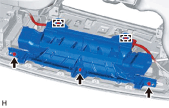
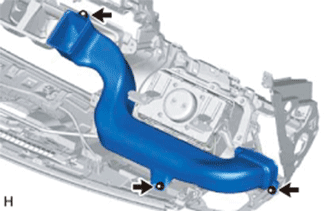
REMOVE DEFROSTER NOZZLE ASSEMBLY
-
Detach the clamps.
-
Remove the 3 screws <F> and defroster nozzle assembly.
-
-
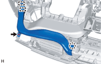
REMOVE NO. 1 HEATER TO REGISTER DUCT
-
Remove the 3 screws <F> and No. 1 heater to register duct.
-
-
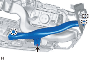
REMOVE NO. 3 HEATER TO REGISTER DUCT
-
Remove the 3 screws <F> and No. 3 heater to register duct.
-
-
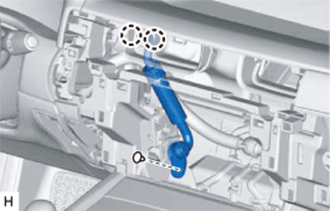
REMOVE AIR DUCT SUB-ASSEMBLY (w/ Ion Generator)
-
Detach the 2 claws.
-
Remove the clip and air duct sub-assembly.
-
-
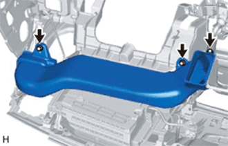
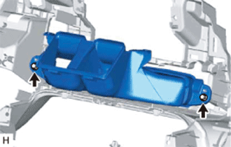
REMOVE NO. 2 HEATER TO REGISTER DUCT
-
Remove the 2 screws <F> and No. 2 heater to register duct.
-
-
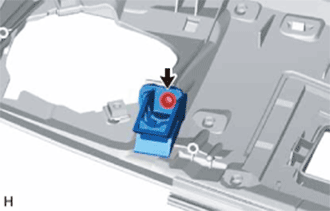
REMOVE NO. 1 INSTRUMENT PANEL PIN
-
Remove the screw <A> and No. 1 instrument panel pin.
-
-
REMOVE NO. 3 INSTRUMENT PANEL PIN
Tech Tips
Use the same procedure described for the No. 1 instrument panel pin.
-
REMOVE NO. 2 INSTRUMENT PAD BRACKET
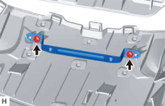
-
Remove the 2 screws <A> and No. 2 instrument pad bracket.
-
-
REMOVE NO. 3 INSTRUMENT PAD BRACKET
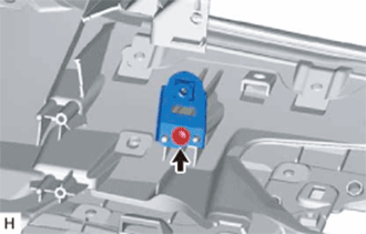
Tech Tips
Use the same procedure for both No. 3 instrument pad brackets.
-
Remove the screw <A> and No. 3 instrument pad bracket.
-
-
REMOVE INSTRUMENT PANEL SAFETY PAD RETAINER
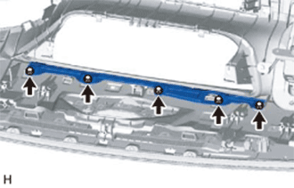
-
Remove the 5 screws <A> and instrument panel safety pad retainer.
-
-
REMOVE NO. 1 INSTRUMENT PANEL CUSHION
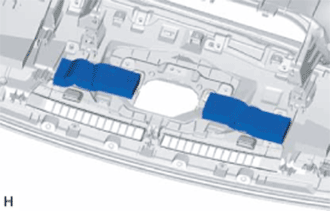
-
Remove the 2 No. 1 instrument panel cushions.
-
-
REMOVE NO. 2 INSTRUMENT PANEL CUSHION (w/o Headup Display)
-
Remove the No. 2 instrument panel cushion.
-
-
REMOVE NO. 3 INSTRUMENT PANEL CUSHION
-
Remove the No. 3 instrument panel cushion.
-
-
REMOVE NO. 4 INSTRUMENT PANEL CUSHION
-
Remove the No. 4 instrument panel cushion.
-
-
REMOVE NO. 5 INSTRUMENT PANEL CUSHION
-
Remove the 2 No. 5 instrument panel cushions.
-
-
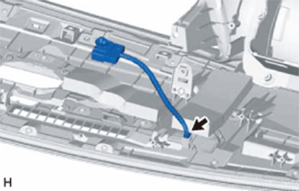
REMOVE NO. 2 INSTRUMENT PANEL WIRE
-
Disconnect the connector and remove the No. 2 instrument panel wire.
-
-
REMOVE AUTOMATIC LIGHT CONTROL SENSOR
-
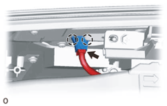
Detach the 2 claws and remove the automatic light control sensor.
-
Disconnect the connector.
-
-
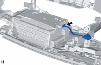
REMOVE NO. 5 INSTRUMENT PANEL WIRE (w/ Headup Display)
-
Disconnect the connector and remove the No. 5 instrument panel wire.
-
-
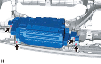
REMOVE COMBINATION METER MIRROR ECU (w/ Headup Display)
-
Remove the 4 screws and combination meter mirror ECU.
-
-
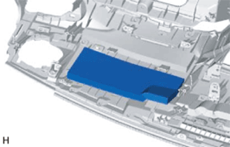
REMOVE INSTRUMENT PANEL PASSENGER AIRBAG ASSEMBLY
CAUTION:
When storing the instrument panel passenger airbag assembly, keep the airbag deployment side facing upward.
-
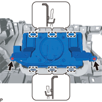
Remove the 2 screws.
-
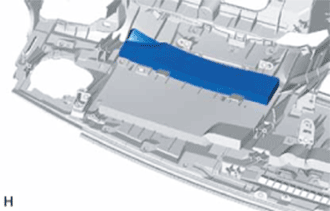
While bending the front of the airbag door, detach the 3 hooks.
-
Detach the 3 hooks from the rear of the airbag door and remove the instrument panel passenger airbag assembly.
-
-
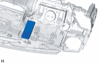
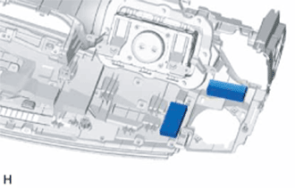
REMOVE NAVIGATION ANTENNA ASSEMBLY (w/ Navigation System)
-
for LHD:
-
for RHD:
-
-
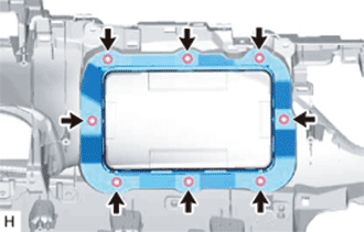
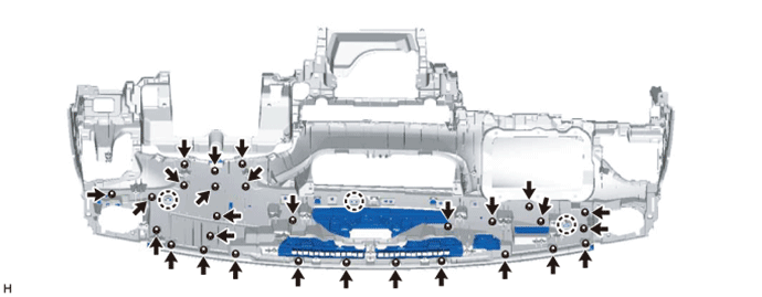
REMOVE INSTRUMENT PANEL SUB-ASSEMBLY
-
Remove the 8 nuts and the installation attachment for the instrument panel passenger airbag.
-
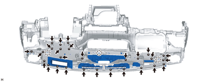
w/ Headup Display:
-
Remove the 27 screws <A>.
-
Detach the 3 claws and remove the instrument panel sub-assembly together with the No. 1 defroster nozzle garnish.
-
Remove the 9 screws <A> and No. 1 defroster nozzle garnish from the instrument panel sub-assembly.
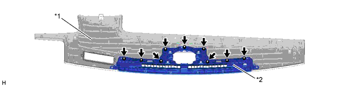
Text in Illustration *1 Instrument Panel Sub-assembly *2 No. 1 Defroster Nozzle Garnish
-
-
w/o Headup Display:
-
Remove the 28 screws <A>.
-
Detach the 3 claws and remove the instrument panel sub-assembly together with the No. 1 defroster nozzle garnish.
-
Remove the 9 screws <A> and No. 1 defroster nozzle garnish from the instrument panel sub-assembly.
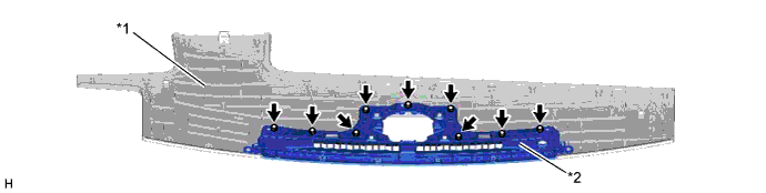
Text in Illustration *1 Instrument Panel Sub-assembly *2 No. 1 Defroster Nozzle Garnish
-
-