REAR SUNSHADE SYSTEM TERMINALS OF ECU

-
CHECK REAR WINDOW SHADE ASSEMBLY (REAR SUNSHADE RELAY)
-
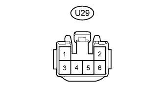
Disconnect the U29 rear window shade assembly connector.
-
Measure the voltage according to the value(s) in the table below.
Terminal No. (Symbol) Wiring Color Terminal Description Condition Specified Condition U29-2 (B) - Body ground P - Body ground Battery power supply Within 60 seconds after engine switch turned off, or engine switch turned on (IG) again after 60 seconds have elapsed from time engine switch turned off 11 to 14 V If the result is not as specified, there may be a malfunction on the wire harness side.
-
Reconnect the U29 rear window shade assembly connector.
-
Measure the voltage according to the value(s) in the table below.
Terminal No. (Symbol) Wiring Color Terminal Description Condition Specified Condition U29-5 (RSW) - Body ground G - Body ground Rear sunshade operation signal
-
Within 60 seconds after engine switch turned off, or engine switch turned on (IG) again after 60 seconds have elapsed from time engine switch turned off
-
Rear control switch (rear sunshade switch) pushed
Below 1 V U29-5 (RSW) - Body ground G - Body ground Rear sunshade operation signal
-
Within 60 seconds after engine switch turned off, or engine switch turned on (IG) again after 60 seconds have elapsed from time engine switch turned off
-
Rear control switch (rear sunshade switch) not pushed
11 to 14 V U29-4 (SW) - Body ground L - Body ground Rear sunshade operation signal
-
Within 60 seconds after engine switch turned off, or engine switch turned on (IG) again after 60 seconds have elapsed from time engine switch turned off
-
Rear sunshade switch pushed
Below 1 V U29-4 (SW) - Body ground L - Body ground Rear sunshade operation signal
-
Within 60 seconds after engine switch turned off, or engine switch turned on (IG) again after 60 seconds have elapsed from time engine switch turned off
-
Rear sunshade switch not pushed
11 to 14 V U29-3 (REV) - Body ground GR - Body ground Reverse position signal
-
Within 60 seconds after engine switch turned off, or engine switch turned on (IG) again after 60 seconds have elapsed from time engine switch turned off
-
Shift lever in P
11 to 14 V U29-3 (REV) - Body ground GR - Body ground Reverse position signal
-
Within 60 seconds after engine switch turned off, or engine switch turned on (IG) again after 60 seconds have elapsed from time engine switch turned off
-
Shift lever in R
Below 1 V -
-
-
CHECK REAR CONTROL SWITCH (w/ Rear Control Switch)
-
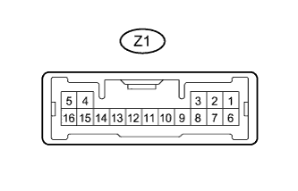
Disconnect the Z1 rear control switch connector.
-
Measure the voltage and resistance of the wire harness side connector.
Terminal No. (Symbol) Wiring Color Terminal Description Condition Specified Condition Z1-1 (+B) - Body ground R - Body ground Power source Always 11 to 14 V Z1-7 (IG+) - Body ground L - Body ground Power source Engine switch on (IG) 11 to 14 V Z1-5 (E) - Body ground W-B - Body ground Ground Always Below 1 Ω If the result is not as specified, there may be a malfunction on the wire harness side.
-
-
CHECK COWL SIDE JUNCTION BLOCK LH, MAIN BODY ECU (MULTIPLEX NETWORK BODY ECU)
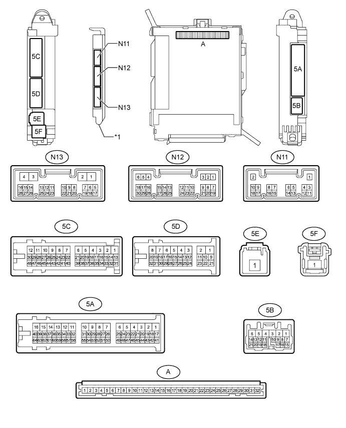
Text in Illustration *1 Main Body ECU (Multiplex Network Body ECU) - -
-
Remove the main body ECU (multiplex network body ECU) from the cowl side junction block LH Click here.
-
Connect the cowl side junction block LH connectors.
-
Measure the voltage and resistance according to the value(s) in the table below.
Terminal No. (Symbol) Wiring Color Terminal Description Condition Specified Condition A-30 (BECU) - Body ground - Battery power supply Always 11 to 14 V A-32 (IG) - Body ground - Engine switch power supply Engine switch on (IG) 11 to 14 V A-32 (IG) - Body ground - Engine switch power supply Engine switch off Below 1 V A-11 (GND1) - Body ground - Ground Always Below 1 Ω If the result is not as specified, there may be a malfunction on the wire harness side or cowl side junction block LH.
-
Install the main body ECU (multiplex network body ECU) Click here.
-
Measure the voltage according to the value(s) in the table below.
Terminal No. (Symbol) Wiring Color Terminal Description Condition Specified Condition N12-15 (REV) - Body ground Y - Body ground Reverse position signal
-
Within 60 seconds after engine switch turned off, or engine switch turned on (IG) again after 60 seconds have elapsed from time engine switch turned off
-
Shift lever in P
11 to 14 V N12-15 (REV) - Body ground Y - Body ground Reverse position signal
-
Within 60 seconds after engine switch turned off, or engine switch turned on (IG) again after 60 seconds have elapsed from time engine switch turned off
-
Shift lever in R
Below 1 V N12-2 (KOFF) - Body ground G - Body ground Battery power supply
-
Within 60 seconds after engine switch turned off, or engine switch turned on (IG) again after 60 seconds have elapsed from time engine switch turned off
-
Rear sunshade switch assembly on
-
Rear control switch (rear sunshade switch) on
Below 1 V N13-13 (CANL) W CAN communication signal - - N13-14 (CANH) R CAN communication signal - - -
-