COMPRESSOR (for AWD) INSTALLATION

-
ADJUST COMPRESSOR OIL
Text in Illustration *1 Drain Bolt
-
When replacing the cooler compressor assembly with a new one, after gradually discharging the refrigerant gas from the service valve, drain the following volume of oil from the new compressor before installation.
Standard (Oil capacity inside a new compressor: 100 + 15 cc (3.38 + 0.51 fl.oz.)) - (Remaining oil amount in the removed compressor + 30 cc (1.01 fl.oz.) = (Oil amount to be removed from the new compressor when replacing. Note
-
When checking the compressor oil level, observe the precautions in the cooler removal/installation.
-
If a new compressor is installed without removing some oil remaining in the pipes of the vehicle, the oil amount becomes excessive. This prevents heat exchange in the refrigerant cycle and causes refrigerant failure.
-
If the volume of oil remaining in the removed compressor and magnetic clutch is too small, check for oil leakage.
-
Be sure to use ND-OIL 8 for compressor oil.
-
-
-
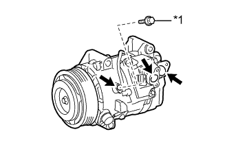
INSTALL COOLER COMPRESSOR ASSEMBLY
-
Using an E8 "torx" socket, install the cooler compressor assembly with the stud bolt.
- Torque:
- 10 N*m { 102 kgf*cm, 7 ft.*lbf }
-
Install the cooler compressor assembly with the 2 bolts and nut.
Tech Tips
Temporarily install the bolts and nut.
-
-
INSTALL OIL FILTER BRACKET SUB-ASSEMBLY
-
Install a new oil filter bracket gasket and the oil filter bracket sub-assembly with the 2 nuts and bolt.
- Torque:
- 21 N*m { 214 kgf*cm, 15 ft.*lbf }
-
Install the wire harness to connect the connector and attach the 2 clamps.
-
-
INSTALL OIL FILTER BRACKET
-
Install the oil filter bracket with the bolt and nut.
- Torque:
- 25 N*m { 250 kgf*cm, 18 ft.*lbf }
Tech Tips
Temporarily install the bolt.
-
-
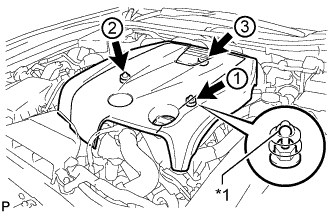
TIGHTEN COOLER COMPRESSOR ASSEMBLY
-
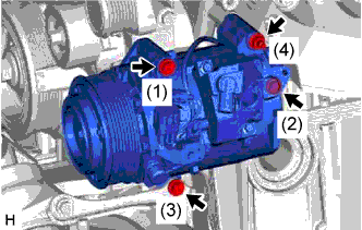
Install the cooler compressor assembly with the 3 bolts and nut.
- Torque:
- 25 N*m { 250 kgf*cm, 18 ft.*lbf }
Note
Tighten the bolts in the order shown in the illustration to install the cooler compressor assembly.
-
-
INSTALL NO. 1 COOLER REFRIGERANT DISCHARGE HOSE
-
Remove the attached vinyl tape from the No. 1 cooler refrigerant discharge hose.
-
Apply sufficient compressor oil (ND-OIL 8) to a new O-ring and the fitting surface of the cooler compressor assembly.
Compressor oil ND-OIL 8 or equivalent -
Install the O-ring on the No. 1 cooler refrigerant discharge hose.
-
Install the No. 1 cooler refrigerant discharge hose on the cooler compressor assembly with the bolt.
- Torque:
- 9.8 N*m { 100 kgf*cm, 87 in.*lbf }
-
-
INSTALL SUCTION HOSE
-
Remove the attached vinyl tape from the suction hose.
-
Apply sufficient compressor oil (ND-OIL 8) to a new O-ring and the fitting surface of the cooler compressor assembly.
Compressor oil ND-OIL 8 or equivalent -
Install the O-ring on the suction hose.
-
Install the suction hose on the cooler compressor assembly with the bolt.
- Torque:
- 9.8 N*m { 100 kgf*cm, 87 in.*lbf }
-
-
INSTALL FAN AND GENERATOR V BELT
-
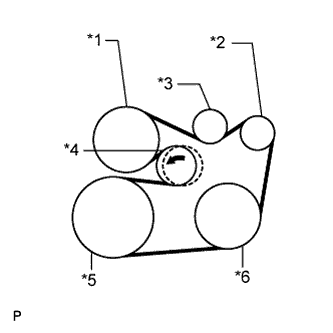
Text in Illustration *1 Engine Water Pump *2 Generator *3 Idler *4 Tensioner *5 Crankshaft *6 A/C Compressor Set the V belt onto every part.
-
While turning the belt tensioner counterclockwise, remove the bar.
Note
-
Put the backside of the V belt on the tensioner pulley and idler pulley.
-
Check that the V belt is properly set to each pulley.
-
-
If it is difficult to install the V belt, perform the following procedure.
-
Put the V belt on every part except the tensioner pulley.
-
Put the V belt on the tensioner pulley while turning the belt tensioner counterclockwise.
Note
-
Put the backside of the V belt on the tensioner pulley and idler pulley.
-
Check that the V belt is properly set to each pulley.
-
-
-
Check that the belt fits properly in the ribbed grooves.
Tech Tips
Make sure to check by hand that the belt has not slipped out of the grooves on the bottom of the pulley.
-
-
INSTALL NO. 1 AIR CLEANER INLET
-
Install the No. 1 air cleaner inlet with the bolt.
- Torque:
- 5.0 N*m { 51 kgf*cm, 44 in.*lbf }
-
-
ADD ENGINE OIL
-
Add clean engine oil.
Note
Do not allow engine oil to adhere to the moving parts of the belt tensioner, as this may cause malfunctions.
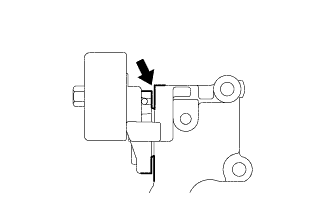
If engine oil is on the location indicated by the arrow, replace the belt tensioner.
Standard Oil Grade Oil Grade Oil Viscosity (SAE)
-
API grade SL "energy-conserving", SM "energy-conserving", SN "resource-conserving" or ILSAC multigrade engine oil
-
5W-30
-
10W-30
API grade SL, SM or SN multigrade engine oil
-
15W-40
-
20W-50
Standard Oil Grade (for Korea) Oil Grade Oil Viscosity (SAE)
-
API grade SL "energy-conserving", SM "energy-conserving", SN "resource-conserving" or ILSAC multigrade engine oil
-
0W-20
-
5W-20
-
5W-30
-
10W-30
API grade SL, SM or SN multigrade engine oil
-
15W-40
-
20W-50
Standard Capacity Item Specified Condition (for 2WD) Specified Condition (for AWD) Drain and refill without oil filter change 5.9 liters (6.2 US. qts., 5.2 Imp. qts.) 6.0 liters (6.3 US. qts., 5.3 Imp. qts.) Drain and refill with oil filter change 6.3 liters (6.7 US. qts., 5.5 Imp. qts.) 6.4 liters (6.7 US. qts., 5.6 Imp. qts.) Dry fill 7.2 liters (7.6 US. qts., 6.3 Imp. qts.) 7.7 liters (8.1 US. qts., 6.8 Imp. qts.) -
-
Install the oil filler cap.
-
-
CHARGE REFRIGERANT
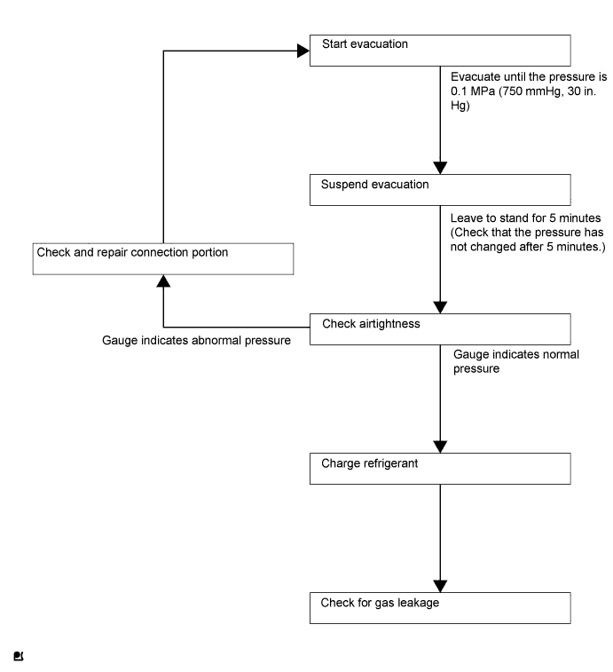
Tech Tips
Charge refrigerant in accordance with the equipment manual.
-
Perform vacuum purging using a vacuum pump.
-
Charge refrigerant HFC-134a (R134a).
- SST
- 09985-20010 ( 09985-02130, 09985-02150, 09985-02090, 09985-02110, 09985-02010, 09985-02050, 09985-02060, 09985-02070 )
Standard 500 +/-50 g (17.64 +/-1.76 oz) 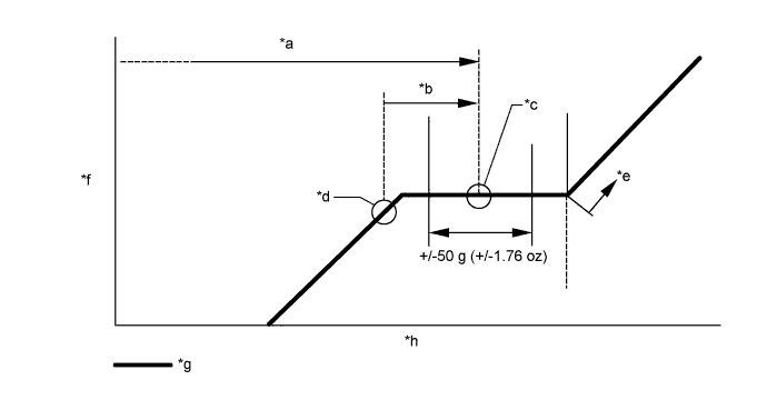
Text in Illustration *a Amount to be charged *b Charge 100 g (3.53 oz) *c Mean value in proper range *d Point where bubbles disappear *e Overcharged *f Pressure *g Sub-cool system *h Refrigerant amount Note
-
Do not operate the cooler compressor before charging refrigerant as the cooler compressor will not work properly without any refrigerant, and will overheat.
-
The system may need to be charged with approximately 100 g (3.53 oz) of refrigerant after bubbles disappear. The refrigerant amount should be checked by measuring its quantity, and not with the sight glass.
-
-
INSPECT FOR OIL LEAK
-
Start the engine. Make sure that no oil leaks from the connection point of the oil filter cap.
-
-
INSPECT ENGINE OIL LEVEL
-
Warm up and stop the engine, and then wait for 5 minutes. The oil level should be between the dipstick's low level mark and full level mark.
If low, check for leakage and add oil up to the full level mark.
Note
Do not add engine oil to above the full level mark.
-
-
WARM UP ENGINE
-
Warm up the engine at less than 1640 rpm for 2 minutes or more after charging the refrigerant.
Note
Be sure to warm up the compressor by turning the A/C switch on after removing and installing the cooler refrigerant lines (including the compressor) to prevent damage to the compressor.
-
-
CHECK FOR REFRIGERANT GAS LEAK
-
After recharging the refrigerant, check for refrigerant gas leakage using a halogen leak detector.
-
Perform the operation observing the following instructions:
-
Stop the engine.
-
Secure good ventilation (the halogen leak detector may react to volatile gases other than refrigerant, such as evaporated gasoline or exhaust gas).
-
Repeat the test 2 or 3 times.
-
Make sure that some refrigerant remains in the refrigeration system.
Tech Tips
When the compressor is off: approximately 392 to 588 kPa (4.0 to 6.0 kgf/cm2, 57 to 85 psi).
-
-
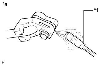
Text in Illustration *1 Halogen Leak Detector *a Check for Leakage Using a halogen leak detector, check the refrigerant line for leakage.
-
If a gas leak is not detected from the drain hose, remove the blower motor control (blower resistor) from the cooling unit. Insert the halogen leak detector sensor into the unit and check for gas leakage.
-
Disconnect the pressure switch connector and wait for approximately 20 minutes. Bring the halogen leak detector close to the pressure switch and check for gas leakage.
-
-
-
INSTALL ENGINE UNDER COVER
-
for 2WD:
-
Install the engine under cover with the 13 screws and 3 clips.
-
-
for AWD:
-
Install the engine under cover with the 10 screws and 3 clips.
-
-
-
INSTALL V-BANK COVER SUB-ASSEMBLY
-
Text in Illustration *1 Tip (Round Portion) Attach the 3 clips in the order shown in the illustration to install the V-bank cover.
Note
-
Securely attach the clips.
-
If the clips are forcibly attached or struck with an object, they may be damaged.
-
Do not apply any oil to the tips (round portions).
-
-
-
INSTALL COOL AIR INTAKE DUCT SEAL
-
Install the cool air intake duct seal with the 7 clips.
-
-
INSTALL ENGINE ROOM SIDE COVER
-
Install the engine room side cover with the 4 clips.
-