COMPRESSOR (for 2WD) INSTALLATION

-
ADJUST COMPRESSOR OIL
-
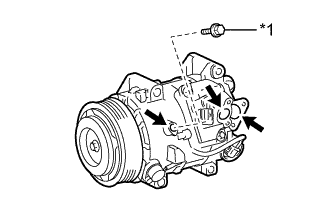
Text in Illustration *1 Drain Bolt (Washer) for HFC-134a (R134a):
-
When replacing the cooler compressor assembly with a new one, after gradually discharging the refrigerant gas from the service valve, drain the following volume of oil from the new cooler compressor assembly before installation.
Standard (Oil capacity inside a new cooler compressor assembly: 100 + 15 cc (3.38 + 0.51 fl.oz.)) - (Remaining oil amount in the removed cooler compressor assembly + 30 cc (1.01 fl.oz. ) = (Oil amount to be removed from the new cooler compressor assembly when replacing. Note
-
When checking the compressor oil level, observe the precautions in the cooler removal/installation.
-
If a new cooler compressor assembly is installed without removing some oil remaining in the pipes of the vehicle, the oil amount becomes excessive. This prevents heat exchange in the refrigerant cycle and causes refrigerant failure.
-
If the volume of oil remaining in the removed cooler compressor assembly and magnetic clutch is too small, check for oil leakage.
-
Be sure to use ND-OIL 8 for compressor oil.
-
-
-
Text in Illustration *1 Drain Bolt (Washer) for HFO-1234yf (R1234yf):
-
When replacing the cooler compressor assembly with a new one, after gradually discharging the refrigerant gas from the service valve, drain the following volume of oil from the new cooler compressor assembly before installation.
Standard (Oil capacity inside a new cooler compressor assembly: 100 + 15 cc (3.38 + 0.51 fl.oz.)) - (Remaining oil amount in the removed cooler compressor assembly + 30 cc (1.01 fl.oz. ) = (Oil amount to be removed from the new cooler compressor assembly when replacing. Note
-
When checking the compressor oil level, observe the precautions in the cooler removal/installation.
-
If a new cooler compressor assembly is installed without removing some oil remaining in the pipes of the vehicle, the oil amount becomes excessive. This prevents heat exchange in the refrigerant cycle and causes refrigerant failure.
-
If the volume of oil remaining in the removed cooler compressor assembly and magnetic clutch is too small, check for oil leakage.
-
Be sure to use ND-OIL 12 for compressor oil.
-
-
-
-
INSTALL COOLER COMPRESSOR ASSEMBLY
-
Using an E8 "torx" socket, install the cooler compressor assembly with the stud bolt.
- Torque:
- 10 N*m { 102 kgf*cm, 7 ft.*lbf }
-
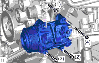
Install the cooler compressor assembly with the 3 bolts and nut.
- Torque:
- for bolt
- 25 N*m { 250 kgf*cm, 18 ft.*lbf }
- for nut
- 25 N*m { 250 kgf*cm, 18 ft.*lbf }
Note
Tighten the bolts in the order shown in the illustration to install the cooler compressor assembly.
-
-
INSTALL NO. 1 COOLER REFRIGERANT DISCHARGE HOSE
-
Remove the attached vinyl tape from the No. 1 cooler refrigerant discharge hose.
-
for HFC-134a (R134a):
Apply sufficient compressor oil (ND-OIL 8) to a new O-ring and the fitting surface of the cooler compressor assembly.
Compressor oil ND-OIL 8 or equivalent -
for HFO-1234yf (R1234yf):
Apply sufficient compressor oil (ND-OIL 12) to a new O-ring and the fitting surface of the cooler compressor assembly.
Compressor oil ND-OIL 12 or equivalent -
Install the O-ring on the No. 1 cooler refrigerant discharge hose.
-
Install the No. 1 cooler refrigerant discharge hose on the cooler compressor assembly with the bolt.
- Torque:
- 9.8 N*m { 100 kgf*cm, 87 in.*lbf }
-
-
INSTALL SUCTION HOSE
-
Remove the attached vinyl tape from the suction hose.
-
for HFC-134a (R134a):
Apply sufficient compressor oil (ND-OIL 8) to a new O-ring and the fitting surface of the cooler compressor assembly.
Compressor oil ND-OIL 8 or equivalent -
for HFO-1234yf (R1234yf):
Apply sufficient compressor oil (ND-OIL 12) to a new O-ring and the fitting surface of the cooler compressor assembly.
Compressor oil ND-OIL 12 or equivalent -
Install the O-ring on the suction hose.
-
Install the suction hose on the cooler compressor assembly with the bolt.
- Torque:
- 9.8 N*m { 100 kgf*cm, 87 in.*lbf }
-
-
INSTALL FAN AND GENERATOR V BELT
-
for 2GR-FSE:
-
for 4GR-FSE:
-
-
INSTALL REAR ENGINE UNDER COVER LH
-
Install the rear engine under cover LH with the screw.
-
-
INSTALL ENGINE UNDER COVER
-
for 2WD:
-
Install the engine under cover with the 13 screws and 3 clips.
-
-
for AWD:
-
Install the engine under cover with the 10 screws and 3 clips.
-
-
-
INSTALL NO. 1 AIR CLEANER INLET
-
Install the No. 1 air cleaner inlet with the bolt.
- Torque:
- 5.0 N*m { 51 kgf*cm, 44 in.*lbf }
-
-
CHARGE REFRIGERANT
-
for HFC-134a (R134a):
-
for HFO-1234yf (R1234yf):
-
-
WARM UP ENGINE
-
for HFC-134a (R134a):
-
for HFO-1234yf (R1234yf):
-
-
CHECK FOR REFRIGERANT GAS LEAK
-
for HFC-134a (R134a):
-
for HFO-1234yf (R1234yf):
-
-
INSTALL V-BANK COVER SUB-ASSEMBLY
-
for 2GR-FSE:
-
for 4GR-FSE:
-
-
INSTALL COOL AIR INTAKE DUCT SEAL
-
Install the cool air intake duct seal with the 7 clips.
-
-
INSTALL ENGINE ROOM COVER SIDE
-
Install the engine room side cover with the 4 clips.
-