HUMIDITY SENSOR REMOVAL

-
REMOVE FRONT ROOF TOP GARNISH
-
w/ Night View System:
-
Using a moulding remover, detach the 2 claws A.
-
Using a moulding remover, detach the 2 clips A.
Tech Tips
When the 2 clips A are detached, claw B, guide B and the fastener may also become detached.
-
Detach the 2 clips B.
-
Move the hooks of the 2 guides A forward, disconnect the connector, and remove the front roof garnish together with the map light assembly.
Note
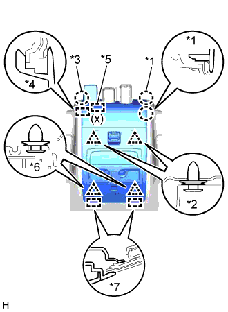
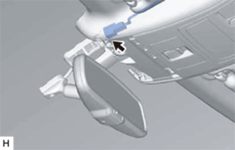
When removing and installing the front roof top garnish, do not apply force to the camera sensor located at (x).
Tech Tips
If the claw B, guide B, and fastener do not become detached when the 2 clips labeled A are detached, detach claw B, guide B and the fastener to remove the front roof top garnish together with the map light assembly.
-
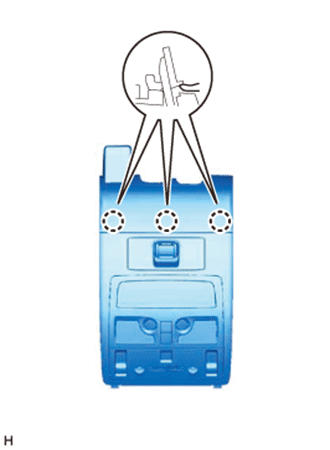
Text in Illustration *1 Claw A *2 Clip A *3 Claw B *4 Guide B *5 Fastener *6 Clip B *7 Guide A Detach the 3 claws on the back of the front roof top garnish and map light assembly, and disconnect the front roof top garnish and map light assembly.
-
-
w/o Night View System:
-
Using a moulding remover, detach the 2 claws A.
-
Using a moulding remover, detach the 2 clips A.
Tech Tips
When the 2 clips A are detached, claw B and guide B may also become detached.
-
Detach the 2 clips B.
-
Move the hooks of the 2 guides A forward, disconnect the connector, and remove the front roof garnish together with the map light assembly.
Note
w/ Lane Keeping Assist System:
When removing and installing the front roof top garnish, do not apply force to the camera sensor located at (x).
Tech Tips
If the claw B and guide B do not become detached when the 2 clips labeled A are detached, detach claw B and guide B to remove the front roof top garnish together with the map light assembly.
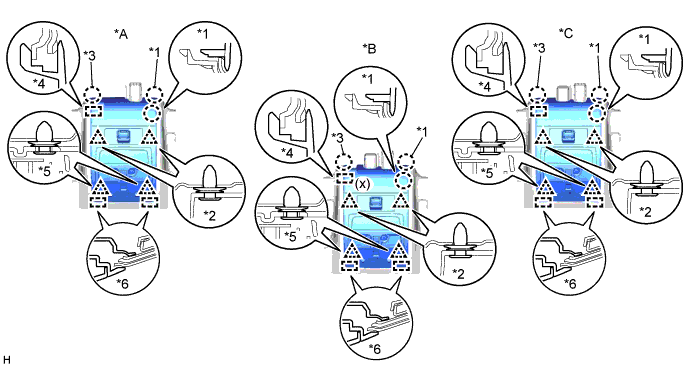
Text in Illustration *A for Standard *B w/ Lane Keeping Assist System *C w/ Rain Sensor - - *1 Claw A *2 Clip A *3 Claw B *4 Guide B *5 Clip B *6 Guide A -
Detach the 3 claws on the back of the front roof top garnish and map light assembly, and disconnect the front roof top garnish and map light assembly.
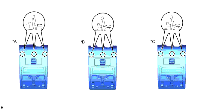
Text in Illustration *A for Standard *B w/ Lane Keeping Assist System *C w/ Rain Sensor - -
-
-
-
REMOVE AIR CONDITIONING THERMISTOR ASSEMBLY
-
Disconnect the connector.
-
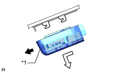
Text in Illustration *1 Stopper Release the stopper by pulling it down.
-
Remove the air conditioning thermistor assembly (humidity sensor) as shown in the illustration.
-