AIR CONDITIONING SYSTEM ECO Switch Circuit
DESCRIPTION
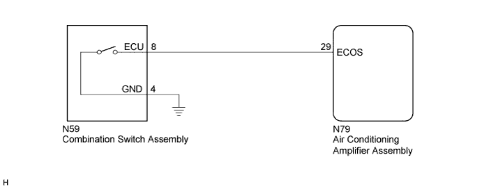
When the combination switch is turned to ECO position, the air conditioning amplifier assembly controls the air conditioning system to enhance fuel efficiency.
WIRING DIAGRAM
INSPECTION PROCEDURE
Note
-
When the battery is disconnected or the air conditioning amplifier assembly is replaced, be sure to perform servo motor initialization Click here.
-
Before disconnecting the cable form the negative (-) battery terminal or replacing the air conditioning amplifier assembly, record the last operation state of the air conditioning for each transmitter. After replacement, it is necessary to perform memory registration for each transmitter Click here.
PROCEDURE
-
READ VALUE USING GTS (ECO SWITCH)
-
Connect the GTS to the DLC3.
-
Turn the engine switch on (IG).
-
Turn the GTS on.
-
Enter the following menus: Body Electrical / Air Conditioner / Data List Click here.
-
Check the values by referring to the table below.
Air Conditioner Tester Display Measurement Item/Range Control Range Diagnostic Note ECO Switch Combination switch assembly /
OFF or ON
ON: Combination switch assembly being turned and held at ECO position
OFF: Combination switch assembly not turned
- OK The combination switch assembly condition displayed on the GTS changes with the actual switch operation.
NG 
CHECK HARNESS AND CONNECTOR (COMBINATION SWITCH ASSEMBLY - AIR CONDITIONING AMPLIFIER ASSEMBLY AND BODY GROUND) Click here
OK 
REPLACE AIR CONDITIONING AMPLIFIER ASSEMBLY Click here
-
-
CHECK HARNESS AND CONNECTOR (COMBINATION SWITCH ASSEMBLY - AIR CONDITIONING AMPLIFIER ASSEMBLY AND BODY GROUND)
-
Disconnect the N59 combination switch assembly connector.
-
Disconnect the N79 air conditioning amplifier assembly connector.
-
Measure the resistance according to the value(s) in the table below.
Standard Resistance Tester Connection Condition Specified Condition N59-8 (ECU) - N79-29 (ECOS) Always Below 1 Ω N59-4 (GND) - Body ground Always Below 1 Ω N59-8 (ECU) - Body ground Always 10 kΩ or higher N59-8 (ECU) - N59-4 (GND) Always 10 kΩ or higher
NG 
REPAIR OR REPLACE HARNESS OR CONNECTOR
OK 
-
-
CHECK AIR CONDITIONING AMPLIFIER ASSEMBLY
-
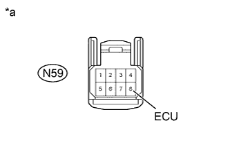
Text in Illustration *a Front view of harness connector
(to Combination Switch Assembly)
Reconnect the N79 air conditioning amplifier assembly connector.
-
Measure the voltage according to the value(s) in the table below.
Standard Voltage Tester Connection Switch Condition Specified Condition N59-8 (ECU) - Body ground Engine switch off Below 1 V N59-8 (ECU) - Body ground Engine switch on (IG) 11 to 14 V
NG
REPLACE AIR CONDITIONING AMPLIFIER ASSEMBLY Click here
OK
-
-
INSPECT COMBINATION SWITCH ASSEMBLY
-
Remove the combination switch assembly.
-
for A760E: Click here.
-
for A760H: Click here.
-
for A960E: Click here.
-
-
Inspect the combination switch assembly Click here.
Result Result Proceed to OK A NG (for A760E) B NG (for A760H) C NG (for A960E) D
B
REPLACE COMBINATION SWITCH ASSEMBLY Click here
C
REPLACE COMBINATION SWITCH ASSEMBLY Click here
D
REPLACE COMBINATION SWITCH ASSEMBLY Click here
A
REPLACE AIR CONDITIONING AMPLIFIER ASSEMBLY Click here
-