AIR CONDITIONING SYSTEM Air Conditioning Compressor Magnetic Clutch Circuit
DESCRIPTION
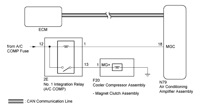
The ECM sends the magnet clutch on permitted signal to the air conditioning amplifier assembly via CAN communication system.
When the air conditioning amplifier assembly is turned on, a magnetic clutch on signal is sent from the MGC terminal of the air conditioning amplifier assembly. Then, the A/C COMP relay turns on to operate the magnetic clutch assembly.
WIRING DIAGRAM
INSPECTION PROCEDURE
Note
-
When the battery is disconnected or the air conditioning amplifier assembly is replaced, be sure to perform servo motor initialization Click here.
-
Inspect the fuses for circuits related to this system before performing the following inspection procedure.
-
Before disconnecting the cable form the negative (-) battery terminal or replacing the air conditioning amplifier assembly, record the last operation state of the air conditioning for each transmitter. After replacement, it is necessary to perform memory registration for each transmitter Click here.
PROCEDURE
-
CHECK CAN COMMUNICATION SYSTEM
-
Use the GTS to check if the CAN communication system is functioning normally.
-
for LHD: Click here.
-
for RHD: Click here.
Result Result Proceed to CAN DTC is not output A CAN DTC is output (for LHD) B CAN DTC is output (for RHD) C -
B 
GO TO CAN COMMUNICATION SYSTEM Click here
C
GO TO CAN COMMUNICATION SYSTEM Click here
A 
-
-
INSPECT NO. 1 INTEGRATION RELAY
-
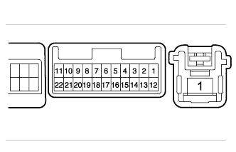
Remove the No. 1 integration relay.
-
Measure the voltage according to the value(s) in the table below.
Standard Voltage Tester Connection Condition Specified Condition 13 - Body ground Battery voltage is not applied to terminals 12 and 1 Below 1 V 13 - Body ground Battery voltage is applied to terminals 12 and 1 11 to 14 V
NG
REPLACE NO. 1 INTEGRATION RELAY
OK
-
-
CHECK HARNESS AND CONNECTOR (NO. 1 INTEGRATION RELAY - AIR CONDITIONING AMPLIFIER, COOLER COMPRESSOR ASSEMBLY AND BATTERY)
-
Disconnect the N79 air conditioning amplifier assembly connector.
-
Disconnect the F20 cooler compressor assembly connector.
-
Measure the voltage according to the value(s) in the table below.
Standard Voltage Tester Connection Condition Specified Condition 2E-12 - Body ground Always 11 to 14 V -
Measure the resistance according to the value(s) in the table below.
Standard Resistance Tester Connection Condition Specified Condition 2E-1 - N79-18 (MGC) Always Below 1 Ω 2E-13 - F20-1 (MG+) Always Below 1 Ω 2E-1 - Body ground Always 10 kΩ or higher 2E-13 - Body ground Always 10 kΩ or higher
NG
REPAIR OR REPLACE HARNESS OR CONNECTOR
OK
-
-
CHECK AIR CONDITIONING AMPLIFIER ASSEMBLY
-
Reconnect the air conditioning amplifier assembly connector.
-
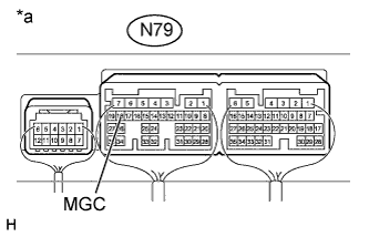
Text in Illustration *a Component with harness connected
(Air Conditioning Amplifier Assembly)
Remove the air conditioning amplifier assembly with connectors still connected Click here.
-
Measure the voltage according to the value(s) in the table below.
Standard Voltage Tester Connection Condition Specified Condition N79-18 (MGC) - Body ground
-
Engine running
-
Blower switch: Lo
-
A/C switch: off
11 to 14 V N79-18 (MGC) - Body ground
-
Engine running
-
Blower switch: Lo
-
A/C switch: on
Below 1 V -
NG 
CHECK AIR CONDITIONING AMPLIFIER ASSEMBLY Click here
OK
-
-
INSPECT MAGNET CLUTCH ASSEMBLY
-
Remove the magnet clutch assembly.
-
for 2WD: Click here.
-
for AWD: Click here.
-
-
Inspect the magnet clutch assembly.
-
for 2WD: Click here.
-
for AWD: Click here.
Result Result Proceed to OK A NG (for 2WD) B NG (for AWD) C -
B
REPLACE MAGNET CLUTCH ASSEMBLY Click here
C
REPLACE MAGNET CLUTCH ASSEMBLY Click here
A 
PROCEED TO NEXT SUSPECTED AREA SHOWN IN PROBLEM SYMPTOMS TABLE Click here
-
-
CHECK AIR CONDITIONING AMPLIFIER ASSEMBLY
-
Replace the air conditioning amplifier assembly with a new or normally functioning one Click here.
-
Check the air conditioning system to check it functions properly.
OK Air conditioning system functions operate normally. Result Result Proceed to OK A NG (for 2GR-FSE) B NG (for 4GR-FSE) C
B
GO TO SFI SYSTEM Click here
C
GO TO SFI SYSTEM Click here
A
END (AIR CONDITIONING AMPLIFIER ASSEMBLY WAS DEFECTIVE)
-