AIR CONDITIONING SYSTEM, Diagnostic DTC:B14AA

| DTC Code | DTC Name |
|---|---|
| B14AA | Glass Humidity Sensor Circuit |
DESCRIPTION
The air conditioner thermistor assembly is installed to the glass window and detects the humidity in the cabin for use in the heater and air conditioner "AUTO" operation. The voltage of the air conditioner thermistor assembly changes according to changes in the humidity in the cabin. The air conditioning amplifier assembly monitors changes in the voltage.
The glass humidity sensor is integrated with the air conditioning thermistor assembly.
| DTC No. | DTC Detection Condition | Trouble Area |
|---|---|---|
| B14AA | Open or short in glass humidity sensor circuit |
|
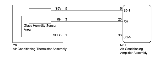
WIRING DIAGRAM
INSPECTION PROCEDURE
Note
-
The whole air conditioning thermistor assembly should be replaced if the glass temperature sensor is malfunctioning.
-
When the battery is disconnected or the air conditioning amplifier assembly is replaced, be sure to perform servo motor initialization Click here.
-
Before disconnecting the cable form the negative (-) battery terminal or replacing the air conditioning amplifier assembly, record the last operation state of the air conditioning for each transmitter. After replacement, it is necessary to perform memory registration for each transmitter Click here.
PROCEDURE
-
READ VALUE USING GTS (GLASS HUMIDITY)
-
Connect the GTS to the DLC3.
-
Turn the engine switch on (IG).
-
Turn the GTS on.
-
Enter the following menus: Body Electrical / Air Conditioner / Data List Click here.
-
Check the value(s) by referring to the table below.
Air Conditioner Tester Display Measurement Item/Range Normal Condition Diagnostic Note Glass Humidity Glass humidity/
Min.: 0%, Max.: 100%
Actual glass humidity displayed - OK The display is as specified in the Normal Condition column. Result Result Proceed to NG A OK (When troubleshooting according to Problem Symptoms Table) B OK (When troubleshooting according to the DTC) C
B 
PROCEED TO NEXT SUSPECTED AREA SHOWN IN PROBLEM SYMPTOMS TABLE Click here
C
REPLACE AIR CONDITIONING AMPLIFIER ASSEMBLY Click here
A 
-
-
CHECK HARNESS AND CONNECTOR (AIR CONDITIONING AMPLIFIER ASSEMBLY - AIR CONDITIONING THERMISTOR ASSEMBLY)
-
Disconnect the Y6 air conditioning thermistor assembly connector.
-
Disconnect the N81 air conditioning amplifier assembly connector.
-
Measure the resistance according to the value(s) in the table below.
Standard Resistance Tester Connection Condition Specified Condition Y6-5 (S5V) - N81-5 (S5-1) Always Below 1 Ω Y6-3 (RH) - N81-23 (RH) Always Below 1 Ω Y6-1 (SEG3) - N81-33 (SG-5) Always Below 1 Ω Y6-5 (S5V) - Body ground Always 10 kΩ or higher Y6-3 (RH) - Body ground Always 10 kΩ or higher Y6-1 (SEG3) - Body ground Always 10 kΩ or higher Y6-5 (S5V) - Y6-1 (SEG3) Always 10 kΩ or higher Y6-3 (RH) - Y6-1 (SEG3) Always 10 kΩ or higher
NG
REPAIR OR REPLACE HARNESS OR CONNECTOR
OK
-
-
CHECK AIR CONDITIONING AMPLIFIER ASSEMBLY
-
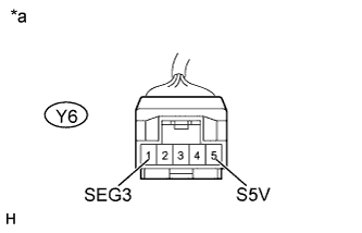
Text in Illustration *a Front view of wire harness connector
(to Air Conditioning Thermistor Assembly)
Reconnect the N81 air conditioning amplifier assembly connector.
-
Measure the voltage according to the value(s) in the table below.
Standard Voltage Tester Connection Switch Condition Specified Condition Y6-5 (S5V) - Body ground Engine switch on (IG) 4.75 to 5.25 V Y6-5 (S5V) - Body ground Engine switch off Below 1 V -
Measure the resistance according to the value(s) in the table below.
Standard Resistance Tester Connection Condition Specified Condition Y6-1 (SEG3) - Body ground Always Below 1 Ω
NG
REPLACE AIR CONDITIONING AMPLIFIER ASSEMBLY Click here
OK
-
-
INSPECT AIR CONDITIONING THERMISTOR ASSEMBLY
-
Remove the air conditioning thermistor assembly Click here.
-
Inspect the air conditioning thermistor assembly Click here.
NG
REPLACE AIR CONDITIONING THERMISTOR ASSEMBLY Click here
OK 
REPLACE AIR CONDITIONING AMPLIFIER ASSEMBLY Click here
-