PARK / NEUTRAL POSITION SWITCH INSTALLATION

-
INSTALL PARK/NEUTRAL POSITION SWITCH ASSEMBLY
Tech Tips
Make sure that the manual valve lever shaft has not been rotated prior to installing the park/neutral position switch assembly as the detent spring may become detached from the manual valve lever shaft.
-
Clean the bolt and the bolt hole.
-
Apply adhesive to 2 or 3 threads on the end of the bolt.
Adhesive Toyota Genuine Adhesive 1344, Three Bond 1344 or equivalent -
Temporarily install the park/neutral position switch assembly with the bolt.
Tech Tips
Tighten the bolt to the specified torque when adjusting the park/neutral position switch assembly.
-
Install a new lock washer and the nut to the park/ neutral position switch assembly.
- Torque:
- 6.9 N*m { 70 kgf*cm, 61 in.*lbf }
-
Temporarily install the transmission control shaft lever RH.
-
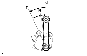
Turn the transmission control shaft lever RH counterclockwise until it stops, and turn it clockwise 2 notches to set it to the N position.
-
Remove the transmission control shaft lever RH.
-
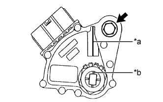
Text in Illustration *a Neutral Basic Line *b Groove Align the neutral basic line with the groove as shown in the illustration, and tighten the bolt.
- Torque:
- 13 N*m { 130 kgf*cm, 9 ft.*lbf }
-
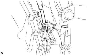
Using a screwdriver, bend the tabs of the lock washer.
-
Connect the park/neutral position switch connector.
-
-
INSTALL TRANSMISSION CONTROL SHAFT LEVER RH
-
Install the transmission control shaft lever RH and spring washer with the nut.
- Torque:
- 16 N*m { 160 kgf*cm, 12 ft.*lbf }
-
-
CONNECT FLOOR SHIFT GEAR SHIFTING ROD SUB-ASSEMBLY
-
Connect the floor shift gear shifting rod sub-assembly to the transmission control shaft lever RH with the pin.
-
Install a new clip.
-
-
INSPECT SHIFT LEVER POSITION
-
When moving the shift lever from P to R with the engine switch on (IG) and the brake pedal depressed, make sure that the shift lever moves smoothly and correctly into the position.
-
Start the engine and make sure that the vehicle moves forward when moving the shift lever from N to D and moves rearward when moving the shift lever to R.
If the operation cannot be done as specified, inspect the park/neutral position switch assembly and check the shift lever assembly installation condition.
-
-
INSPECT PARK/NEUTRAL POSITION SWITCH ASSEMBLY
-
Apply the parking brake.
-
Turn the engine switch on (IG).
-
Depress the brake pedal and check that the engine starts when the shift lever is in N or P, but does not start in other positions.
-
Check that the back-up light comes on and the reverse warning buzzer sounds when the shift lever is in R, but the light and buzzer do not operate in other positions.
If a failure is found, check the park/neutral position switch for continuity.
-
-
INSTALL NO. 2 ENGINE UNDER COVER
-
Install the No. 2 engine under cover with the 4 screws and 2 grommets.
-
-
INSTALL FRONT SUSPENSION MEMBER BRACE
-
Install the front suspension member brace with the clip and 4 bolts.
- Torque:
- 52 N*m { 530 kgf*cm, 38 ft.*lbf }
-