AUTOMATIC TRANSMISSION SYSTEM Shift Paddle Switch Circuit
DESCRIPTION
When moving the shift lever into the M position using the transmission control switch, it is possible to switch the shift range position between "1" (first range) and "6" (sixth range).
Shifting up "+" once raises one shift range position, and shifting down "-" lowers one shift range position.
When the shift lever is in D, operating the "-" side shift paddle switch will cause the transmission to enter fixed range mode which restricts the highest gear. By operating the shift paddle switches "+" (UP) or "-" (DOWN), the shift range can be changed.
When the vehicle is being operated in D position (fixed range mode), if the vehicle is stopped or the accelerator pedal is kept steady for a certain period of time with the transmission in the same gear, the vehicle will change back automatically to normal D position operation.
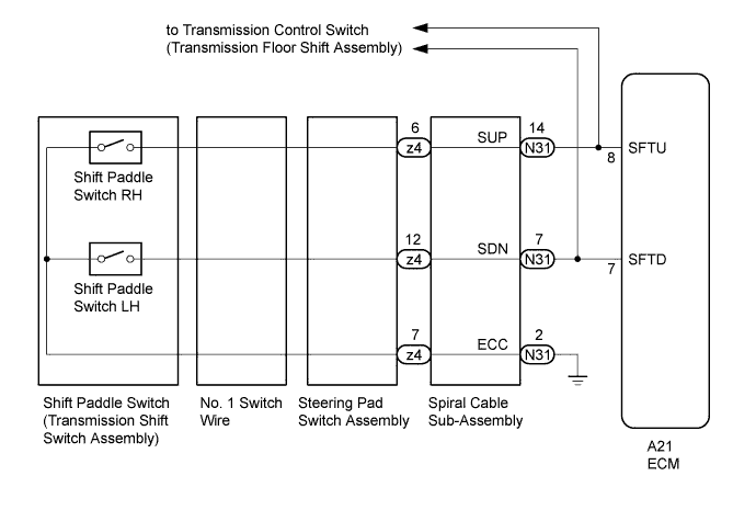
WIRING DIAGRAM
INSPECTION PROCEDURE
PROCEDURE
-
CHECK HARNESS AND CONNECTOR (SPIRAL CABLE - BODY GROUND)
-
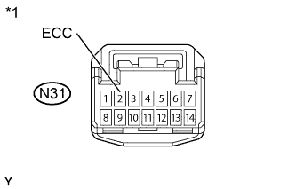
Text in Illustration *1 Front view of wire harness connector
(to Spiral Cable Sub-Assembly)
Disconnect the spiral cable connector.
-
Measure the resistance according to the value(s) in the table below.
Standard resistance Tester Connection Specified Condition N31-2 (ECC) - Body ground Below 1 Ω
NG 
REPAIR OR REPLACE HARNESS OR CONNECTOR
OK 
-
-
INSPECT SPIRAL CABLE SUB-ASSEMBLY
-
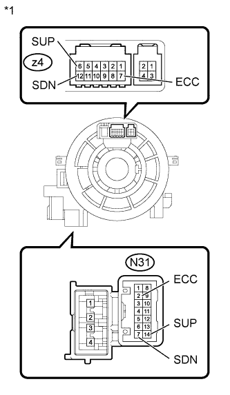
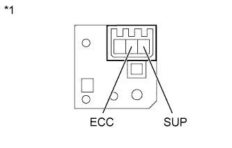
Text in Illustration *1 Component without harness connected
(Spiral Cable Sub-Assembly)
Remove the spiral cable sub-assembly Click here.
-
Measure the resistance according to the value(s) in the table below.
Standard resistance Tester Connection Condition Specified Condition N31-2 (ECC) - z4-7 (ECC) Always Below 1 Ω N31-14 (SUP) - z4-6 (SUP) Always Below 1 Ω N31-7 (SDN) - z4-12 (SDN) Always Below 1 Ω
NG
REPLACE SPIRAL CABLE SUB-ASSEMBLY Click here
OK
-
-
INSPECT TRANSMISSION SHIFT SWITCH ASSEMBLY LH
-
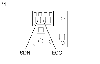
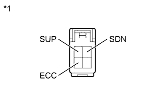
Text in Illustration *1 Component without harness connected
(Transmission Shift Switch Assembly LH)
Disconnect the No. 1 switch wire connector from the transmission shift switch LH.
-
Measure the resistance between each terminal when the paddle shift is moved to each position.
Standard resistance Tester Connection Paddle Shift Position Specified Condition SDN - ECC Pull continuously
"-"
(Down shift)
Below 2.5 Ω ↑ Release
"-"
(Down shift)
1 MΩ or higher
NG
REPLACE TRANSMISSION SHIFT SWITCH ASSEMBLY LH Click here
OK
-
-
INSPECT TRANSMISSION SHIFT SWITCH ASSEMBLY RH
-
Text in Illustration *1 Component without harness connected
(Transmission Shift Switch Assembly RH)
Disconnect the No. 1 switch wire connector from the transmission shift switch RH.
-
Measure the resistance between each terminal when the paddle shift is moved to each position.
Standard resistance Tester Connection Paddle Shift Position Specified Condition SUP - ECC Pull continuously
"+"
(Up shift)
Below 2.5 Ω ↑ Release
"+"
(Up shift)
1 MΩ or higher
NG
REPLACE TRANSMISSION SHIFT SWITCH ASSEMBLY RH Click here
OK
-
-
INSPECT NO. 1 SWITCH WIRE
-
Text in Illustration *1 Component without harness connected
(No. 1 switch wire)
Connect the No. 1 switch wire connector to the transmission shift switch.
-
Disconnect the No. 1 switch wire connector from the steering pad switch.
-
Measure the resistance between each terminal when the paddle shift is moved to each postion.
Standard resistance Tester Connection Paddle Shift Position Specified Condition SUP - ECC Pull continuously
"+"
(Up shift)
Below 2.5 Ω ↑ Release
"+"
(Up shift)
1 MΩ or higher SDN - ECC Pull continuously
"-"
(Down shift)
Below 2.5 Ω ↑ Release
"-"
(Down shift)
1 MΩ or higher
NG
REPLACE NO. 1 SWITCH WIRE Click here
OK
-
-
INSPECT STEERING PAD SWITCH ASSEMBLY
-
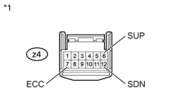
Text in Illustration *1 Component without harness connected
(Steering Pad Switch Assembly)
Connect the No. 1 switch wire connector to the steering pad switch.
-
Measure the resistance between each terminal when the paddle shift is moved to each postion.
Standard resistance Tester Connection Paddle Shift Position Specified Condition z4-6 (SUP) - z4-7 (ECC) Pull continuously
"+"
(Up shift)
Below 2.5 Ω ↑ Release
"+"
(Up shift)
1 MΩ or higher z4-12 (SDN) - z4-7 (ECC) Pull continuously
"-"
(Down shift)
Below 2.5 Ω ↑ Release
"-"
(Down shift)
1 MΩ or higher
NG
REPLACE STEERING PAD SWITCH ASSEMBLY Click here
OK
-
-
CHECK HARNESS AND CONNECTOR (SPIRAL CABLE - ECM)
-
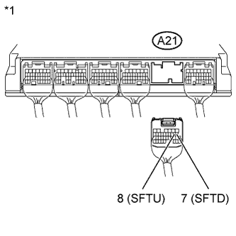
Text in Illustration *1 Rear view of wire harness connector
(to ECM)
Connect the spiral cable connector and steering pad switch connector.
-
Disconnect the ECM connector.
-
Measure the resistance according to the value(s) in the table below when the paddle shift is moved to each position.
Standard resistance Tester Connection Paddle Shift Position Specified Condition A21-8 (SFTU) - Body ground Pull continuously
"+"
(Up shift)
Below 2.5 Ω ↑ Release
"+"
(Up shift)
1 MΩ or higher A21-7 (SFTD) - Body ground Pull continuously
"-"
(Down shift)
Below 2.5 Ω ↑ Release
"-"
(Down shift)
1 MΩ or higher
NG
REPAIR OR REPLACE HARNESS OR CONNECTOR
OK 
REPLACE ECM Click here
-