AUTOMATIC TRANSMISSION SYSTEM, Diagnostic DTC:P2759

| DTC Code | DTC Name |
|---|---|
| P2759 | Torque Converter Clutch Pressure Control Solenoid Control Circuit Electrical (Shift Solenoid Valve SLU) |
DESCRIPTION
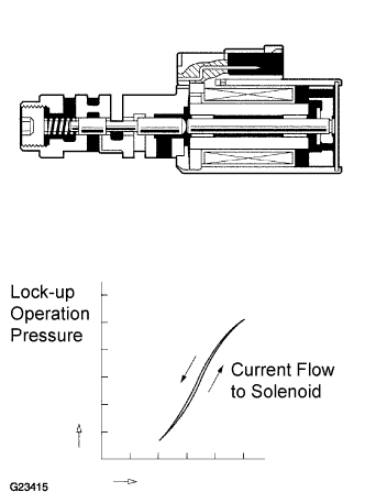
The amount of current flow to the solenoid is controlled by the ECM. During the lock-up operation, if the current increases, the lock-up hydraulic pressure increases.
| DTC No. | DTC Detection Condition | Trouble Area |
|---|---|---|
| P2759 | Open or short is detected in shift solenoid valve SLU circuit for 1 second or more while driving (1-trip detection logic). |
|
MONITOR DESCRIPTION
When an open or short in a shift solenoid valve (SLU) circuit is detected, the ECM determines there is a malfunction. The ECM will turn on the MIL and store this DTC.
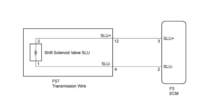
WIRING DIAGRAM
INSPECTION PROCEDURE
PROCEDURE
-
INSPECT TRANSMISSION WIRE (SLU)
-
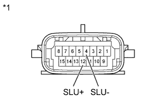
Text in Illustration *1 Component without harness connected
(Transmission Wire)
Disconnect the transmission wire connector from the transmission.
-
Measure the resistance according to the value(s) in the table below.
Standard resistance Tester Connection Specified Condition
20°C (68°F)
12 (SLU+) - 4 (SLU-) 5.0 to 5.6 Ω -
Measure the resistance according to the value(s) in the table below.
Standard resistance (Check for short) Tester Connection Specified Condition 12 (SLU+) - Body ground 10 kΩ or higher 4 (SLU-) - Body ground ↑
NG 
OK 
-
-
CHECK HARNESS AND CONNECTOR (TRANSMISSION WIRE - ECM)
-
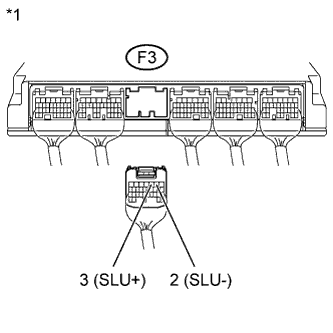
Text in Illustration *1 Rear view of wire harness connector
(to ECM)
Connect the transmission wire connector to the transmission.
-
Disconnect the ECM connector.
-
Measure the resistance according to the value(s) in the table below.
Standard resistance Tester Connection Specified Condition
20°C (68°F)
F3-3 (SLU+) - F3-2 (SLU-) 5.0 to 5.6 Ω -
Measure the resistance according to the value(s) in the table below.
Standard resistance (Check for short) Tester Connection Specified Condition F3-3 (SLU+) - Body ground 10 kΩ or higher F3-2 (SLU-) - Body ground ↑
NG 
REPAIR OR REPLACE HARNESS OR CONNECTOR
OK 
REPLACE ECM Click here
-
-
INSPECT SHIFT SOLENOID VALVE SLU
-
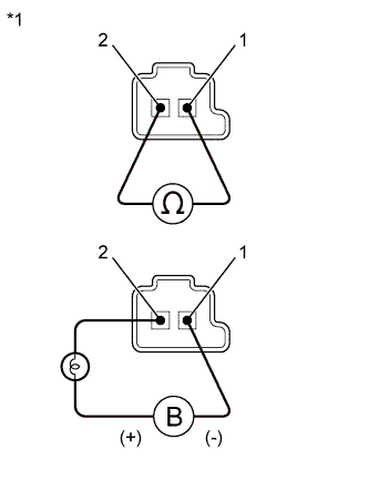
Text in Illustration *1 Shift Solenoid Valve SLU Remove the shift solenoid valve SLU.
-
Measure the resistance according to the value(s) in the table below.
Standard resistance Tester Connection Specified Condition
20°C (68°F)
1 - 2 5.0 to 5.6 Ω -
Connect the positive (+) lead with a 21 W bulb to terminal 2 and the negative (-) lead to terminal 1 of the solenoid valve connector, then check the movement of the valve.
OK The solenoid makes an operating sound.
NG
REPLACE SHIFT SOLENOID VALVE SLU Click here
OK
REPAIR OR REPLACE TRANSMISSION WIRE Click here
-