LANE-KEEPING ASSIST SYSTEM Headlight Dimmer Switch Circuit
DESCRIPTION
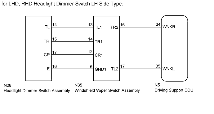
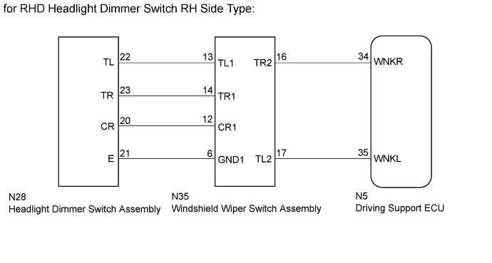
The driving support ECU receives turn signal switch signals from the headlight dimmer switch assembly via the windshield wiper switch and controls the lane keeping assist system.
WIRING DIAGRAM
INSPECTION PROCEDURE
PROCEDURE
-
INSPECT HEADLIGHT DIMMER SWITCH ASSEMBLY
-
Remove the headlight dimmer switch assembly Click here.
-
Inspect the headlight dimmer switch assembly Click here.
NG 
REPLACE HEADLIGHT DIMMER SWITCH ASSEMBLY Click here
OK 
-
-
CHECK HARNESS AND CONNECTOR (HEADLIGHT DIMMER SWITCH ASSEMBLY - WINDSHIELD WIPER SWITCH ASSEMBLY)
-
Disconnect the N28 headlight dimmer switch assembly connector.
-
Disconnect the N35 windshield wiper switch assembly connector.
-
Measure the resistance according to the value(s) in the table below.
Standard Resistance for LHD, RHD Headlight Dimmer Switch LH Side Type Tester Connection Condition Specified Condition N28-14 (TL) - N35-13 (TL1) Always Below 1 Ω N28-15 (TR) - N35-14 (TR1) Always Below 1 Ω N28-16 (E) - N35-6 (GND1) Always Below 1 Ω N28-17 (CR) - N35-12 (CR1) Always Below 1 Ω N28-14 (TL) - Body ground Always 10 kΩ or higher N28-15 (TR) - Body ground Always 10 kΩ or higher N28-16 (E) - Body ground Always 10 kΩ or higher N28-17 (CR) - Body ground Always 10 kΩ or higher for RHD Headlight Dimmer Switch RH Side Type Tester Connection Condition Specified Condition N28-22 (TL) - N35-13 (TL1) Always Below 1 Ω N28-23 (TR) - N35-14 (TR1) Always Below 1 Ω N28-21 (E) - N35-6 (GND1) Always Below 1 Ω N28-20 (CR) - N35-12 (CR1) Always Below 1 Ω N28-22 (TL) - Body ground Always 10 kΩ or higher N28-23 (TR) - Body ground Always 10 kΩ or higher N28-21 (E) - Body ground Always 10 kΩ or higher N28-20 (CR) - Body ground Always 10 kΩ or higher
NG
REPAIR OR REPLACE HARNESS OR CONNECTOR
OK
-
-
CHECK HARNESS AND CONNECTOR (WINDSHIELD WIPER SWITCH ASSEMBLY - DRIVING SUPPORT ECU)
-
Disconnect the N35 windshield wiper switch assembly connector.
-
Disconnect the N5 driving support ECU connector.
-
Measure the resistance according to the value(s) in the table below.
Standard Resistance Tester Connection Condition Specified Condition N35-16 (TR2) - N5-34 (WNKR) Always Below 1 Ω N35-17 (TL2) - N5-35 (WNKL) Always Below 1 Ω N35-16 (TR2) - Body ground Always 10 kΩ or higher N35-17 (TL2) - Body ground Always 10 kΩ or higher
NG
REPAIR OR REPLACE HARNESS OR CONNECTOR
OK 
PROCEED TO NEXT SUSPECTED AREA SHOWN IN PROBLEM SYMPTOMS TABLE Click here
-