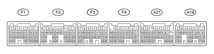
AUTOMATIC TRANSMISSION SYSTEM TERMINALS OF ECM

-
ECM
Tech Tips
Each ECM terminal's standard voltage is shown in the table below.
In the table, first follow the information under "Condition". Look under "Symbols (Terminal No.)" for the terminals to inspected. The standard voltage between the terminals is shown under "Specific Condition".
Use the illustration above as a reference for the ECM terminals.
Terminals No. (Symbols) Wiring Color Terminal Description Condition Specified Condition F1-1 (+BM) - F4-1 (E1) P - BR Power source of throttle motor Always 11 to 14 V A19-7 (BATT) - F4-1 (E1) L - BR Battery (for measuring battery voltage and for ECM memory) Always 11 to 14 V A21-2 (+B) - F4-1 (E1) P - BR Power source of ECM Engine switch on (IG) 11 to 14 V A21-20 (STA) - F4-1 (E1) R - BR Starter signal Cranking 11 to 14 V A19-13 (STP) - F4-1 (E1) R - BR Stop light switch signal Brake pedal is depressed 7.5 to 14 V ↑ ↑ ↑ Brake pedal is released Below 1 V A21-29 (NSW) - F4-1 (E1) G - BR Park neutral switch signal Engine switch on (IG) and shift lever P and N position Below 1 V ↑ ↑ ↑ Engine switch on (IG) and shift lever except P and N position 11 to 14 V F4-12 (P) - F4-1 (E1) B - BR Park position switch signal Engine switch on (IG) and shift lever P position 11 to 14 V ↑ ↑ ↑ Engine switch on (IG) and shift lever except P position Below 1 V F4-11 (R) - F4-1 (E1) R - BR R shift position switch signal Engine switch on (IG) and shift lever R position 11 to 14 V ↑ ↑ ↑ Engine switch on (IG) and shift lever except R position Below 1 V F4-13 (N) - F4-1 (E1) G - BR Neutral position switch signal Engine switch on (IG) and shift lever N position 11 to 14 V ↑ ↑ ↑ Engine switch on (IG) and shift lever except N position Below 1 V F4-14 (D) - F4-1 (E1) W - BR D shift position switch signal Engine switch on (IG) and shift lever D and M position 11 to 14 V ↑ ↑ ↑ Engine switch on (IG) and shift lever except D and M position Below 1 V A21-16 (S) - F4-1 (E1) R - BR M shift position switch signal Engine switch on (IG) and shift lever M position 11 to 14 V ↑ ↑ ↑ Engine switch on (IG) and shift lever except M position Below 1 V A21-8 (SFTU) - F4-1 (E1) Y - BR Up shift switch signal Engine switch on (IG) and shift lever M position 11 to 14 V ↑ ↑ ↑ Engine switch on (IG) and shift lever "+" position (Up shift) Below 1 V ↑ ↑ ↑ Engine switch on (IG) and "+" shift paddle operated and held (up-shift) ↑ A21-7 (SFTD) - F4-1 (E1) W - BR Down shift switch signal Engine switch on (IG) and shift lever M position 11 to 14 V ↑ ↑ ↑ Engine switch on (IG) and shift lever "-" position (Down shift) Below 1 V ↑ ↑ ↑ Engine switch on (IG) and "-" shift paddle operated and held (down-shift) ↑ F1-29 (THO1) - F1-28 (E2) L - BR ATF temperature sensor signal ATF temperature: 115°C (239°F) or more Below 1.5 V F1-3 (SL1+) - F1-2 (SL1-) Y - GR SL1 solenoid signal 5th or 6th gear Pulse generation F1-14 (SL2+) - F1-13 (SL2-) B - G SL2 solenoid signal Engine idle speed Pulse generation F3-5 (SLT+) - F3-4 (SLT-) G - BR SLT solenoid signal Engine idle speed Pulse generation F3-3 (SLU+) - F3-2 (SLU-) R - L SLU solenoid signal 5th (lock-up) or 6th (lock-up) gear Pulse generation F1-5 (S1) - F4-1 (E1) R - BR S1 solenoid signal 1st gear Below 1 V ↑ ↑ ↑ Except 1st gear 11 to 14 V F1-4 (S2) - F4-1 (E1) W - BR S2 solenoid signal 1st, 2nd or 6th gear 11 to 14 V ↑ ↑ ↑ 3rd, 4th or 5th gear Below 1 V A19-9 (S3) - F4-1 (E1) V - BR S3 solenoid signal 1st, 2nd or 3rd gear 11 to 14 V ↑ ↑ ↑ 4th, 5th or 6th gear Below 1 V F4-21 (S4) - F4-1 (E1) L - BR S4 solenoid signal 5th or 6th gear 11 to 14 V ↑ ↑ ↑ 1st, 2nd, 3rd or 4th gear Below 1 V A21-6 (SR) - F4-1 (E1) GR - BR SR solenoid signal 1st, 2nd, 3rd or 4th gear 11 to 14 V ↑ ↑ ↑ 5th or 6th gear Below 1 V F4-16 (NT+) - F4-15 (NT-) R - G Transmission revolution sensor (NT) signal Engine idle speed (P or N position) Pulse generation
(See waveform 1)
A21-33 (SP2+) - A21-32 (SP2-) L - Y Transmission revolution sensor (SP2) signal Vehicle speed 20 km/h (12 mph) Pulse generation
(See waveform 2)
A21-25 (SPCN) - F4-1 (E1) Y - BR Combination switch signal Engine switch on (IG) and combination switch not pushed 11 to 14 V ↑ ↑ ↑ Engine switch on (IG) and combination switch being pushed and held at NORMAL position Below 1 V A19-16 (SPSW)*1 - F4-1 (E1) P - BR Combination switch signal Engine switch on (IG) and combination switch not turned 11 to 14 V ↑ ↑ ↑ Engine switch on (IG) and combination switch being turned and held at SPORT position Below 1 V A21-23 (PWR)*2 - F4-1 (E1) P - BR Combination switch signal Engine switch on (IG) and combination switch not turned 11 to 14 V ↑ ↑ ↑ Engine switch on (IG) and combination switch being turned and held at SPORT position Below 1 V A21-22 (SNWI)*3 - F4-1 (E1) L - BR Combination switch signal Engine switch on (IG) and combination switch (SNOW) not pushed 11 to 14 V ↑ ↑ ↑ Engine switch on (IG) and combination switch (SNOW) pushed Below 1 V A19-14 (KD)*4 - F4-1 (E1) L - BR Kick-down switch signal Engine switch on (IG) and Accelerator pedal is depressed Below 1 V ↑ ↑ ↑ Engine switch on (IG) and Accelerator pedal is released 11 to 14 V A21-14 (CANH) - F4-1 (E1) G - BR CAN communication line Engine switch on (IG) Pulse generation
(See waveform 3)
A21-13 (CANL) - F4-1 (E1) W - BR CAN communication line Engine switch on (IG) Pulse generation
(See waveform 4)
-
*1: w/ Adaptive Variable Suspension
-
*2: w/o Adaptive Variable Suspension
-
*3: w/ SNOW switch
-
*4: w/ Kick down switch assembly
-
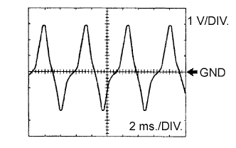
Waveform 1
Reference: Terminal NT+ - NT- Tool setting 1 V/DIV., 2 ms./DIV. Vehicle condition Engine idle speed (P or N position) -
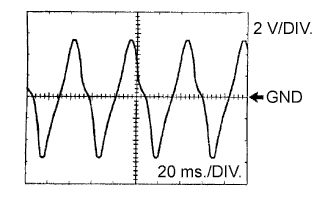
Waveform 2
Reference: Terminal SP2+ - SP2- Tool setting 2 V/DIV., 20 ms./DIV. Vehicle condition Vehicle speed 20 km/h (12 mph) -
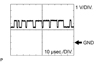
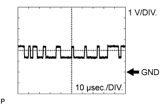
Waveform 3
Reference: Terminal CANH - E1 Tool setting 1 V/DIV., 10 μsec./DIV. Vehicle condition Engine switch on (IG) -
Waveform 4
Reference: Terminal CANL - E1 Tool setting 1 V/DIV., 10 μsec./DIV. Vehicle condition Engine switch on (IG)
-