LANE-KEEPING ASSIST SYSTEM TERMINALS OF ECU

-
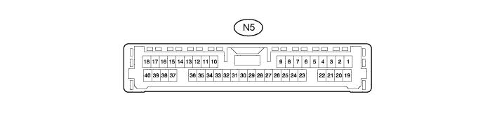
CHECK DRIVING SUPPORT ECU
-
Disconnect the N5 driving support ECU connector.
Note
If a load of more than 10 kg (22 lb.) is placed on the connector, it may break. Do not place more load than is necessary on the connector.
-
Measure the voltage and resistance according to the value(s) in the table below.
Terminal No. (Symbol) Wiring Color Terminal Description Condition Specified Condition N5-2 (CA3H) - N5-25 (GND) G - BR*1
G - W-B*2
CAN communication system Engine switch on (IG) Pulse generation
(See waveform 1)
N5-6 (SPSW) - N5-25 (GND) Y - BR*1
Y - W-B*2
Lane-keeping assist main switch signal Engine switch on (IG),
steering pad switch off
1 MΩ or higher N5-6 (SPSW) - N5-25 (GND) Y - BR*1
Y - W-B*2
Lane-keeping assist main switch signal Engine switch on (IG),
steering pad switch on (Lane-keeping assist main switch on and distance control switch off)
235 to 245 Ω N5-6 (SPSW) - N5-25 (GND) Y - BR*1
Y - W-B*2
Distance control switch signal Engine switch on (IG),
steering pad switch off
1 MΩ or higher N5-6 (SPSW) - N5-25 (GND) Y - BR*1
Y - W-B*2
Distance control switch signal Engine switch on (IG),
steering pad switch on (Lane-keeping assist main switch off and distance control switch on)
Below 2.5 Ω N5-9 (WASH) - N5-25 (GND) B - BR*1
B - W-B*2
Wiper switch signal Engine switch on (IG),
Windshield washer switch off
9 to 14 V N5-9 (WASH) - N5-25 (GND) B - BR*1
B - W-B*2
Wiper switch signal Engine switch on (IG),
Windshield washer switch on
Below 1 V N5-17 (CA2L) - N5-25 (GND) LG - BR*1
LG - W-B*2
CAN communication system Engine switch on (IG) Pulse generation
(See waveform 2)
N5-18 (CA1N) - N5-25 (GND) W - BR*1
W - W-B*2
CAN communication system Engine switch on (IG) Pulse generation
(See waveform 2)
N5-20 (CA3L) - N5-25 (GND) SB - BR*1
SB - W-B*2
CAN communication system Engine switch on (IG) Pulse generation
(See waveform 2)
N5-27 (STP-) - N5-25 (GND) R - BR*1
R - W-B*2
Stop light switch signal input Depress brake pedal 9 to 14 V N5-27 (STP-) - N5-25 (GND) R - BR*1
R - W-B*2
Stop light switch signal input Release brake pedal Below 1 V N5-28 (ST1-) - N5-25 (GND) GR - BR*1
GR - W-B*2
Stop light switch signal input Engine switch on (IG),
release brake pedal
9 to 14 V N5-28 (ST1-) - N5-25 (GND) GR - BR*1
GR - W-B*2
Stop light switch signal input Engine switch on (IG),
depress brake pedal
Below 1 V N5-30 (B) - N5-25 (GND) L - BR*1
L - W-B*2
Power supply Engine switch on (IG) 11 to 14 V N5-30 (B) - N5-25 (GND) L - BR*1
L - W-B*2
Power supply Engine switch off Below 1 V N5-32 (WIP2) - N5-25 (GND) L - BR*1
L - W-B*2
Wiper switch signal Engine switch on (IG),
Windshield wiper switch off
9 to 14 V N5-32 (WIP2) - N5-25 (GND) L - BR*1
L - W-B*2
Wiper switch signal Engine switch on (IG),
Windshield wiper switch Hi
Below 1 V N5-34 (WNKR) - N5-25 (GND) GR - BR*1
GR - W-B*2
Turn switch signal Engine switch on (IG),
Turn signal switch off
9 to 14 V N5-34 (WNKR) - N5-25 (GND) GR - BR*1
GR - W-B*2
Turn switch signal Engine switch on (IG),
Turn signal switch right
Below 1 V N5-35 (WNKL) - N5-25 (GND) G - BR*1
G - W-B*2
Turn switch signal Engine switch on (IG),
Turn signal switch off
9 to 14 V N5-35 (WNKL) - N5-25 (GND) G - BR*1
G - W-B*2
Turn switch signal Engine switch on (IG),
Turn signal switch left
Below 1 V N5-39 (CA2H) - N5-25 (GND) V - BR*1
V - W-B*2
CAN communication system Engine switch on (IG) Pulse generation
(See waveform 1)
N5-40 (CA1P) - N5-25 (GND) G - BR*1
G - W-B*2
CAN communication system Engine switch on (IG) Pulse generation
(See waveform 1)
-
*1: for LHD
-
*2: for RHD
If the result is not as specified, there may be a malfunction on the wire harness side.
-
-
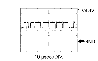
Using an oscilloscope, check waveform 1.
Measurement Condition Item Content Tester Connection
-
N5-2 (CA3H) - N5-25 (GND)
-
N5-39 (CA2H) - N5-25 (GND)
-
N5-40 (CA1P) - N5-25 (GND)
Tool Setting 1 V/DIV., 10 μsec/DIV. Vehicle Condition Engine switch on (IG) -
-
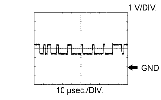
Using an oscilloscope, check waveform 2.
Measurement Condition Item Content Tester Connection
-
N5-17 (CA2L) - N5-25 (GND)
-
N5-18 (CA1N) - N5-25 (GND)
-
N5-20 (CA3L) - N5-25 (GND)
Tool Setting 1 V/DIV., 10 μsec/DIV. Vehicle Condition Engine switch on (IG) -
-
-
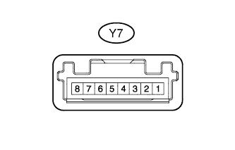
CHECK LANE RECOGNITION CAMERA SENSOR ASSEMBLY
-
Disconnect the Y7 lane recognition camera sensor assembly connector.
-
Measure the voltage and resistance according to the value(s) in the table below.
Terminal No. (Symbol) Wiring Color Terminal Description Condition Specified Condition Y7-4 (GND) - Body ground BR - Body ground Ground Always Below 1 Ω Y7-8 (IGB) - Y7-4 (GND) L - BR Power supply Engine switch on (IG) 11 to 14 V Y7-8 (IGB) - Y7-4 (GND) L - BR Power supply Engine switch off Below 1 V If the result is not as specified, there may be a malfunction on the wire harness side.
-