DYNAMIC RADAR CRUISE CONTROL SYSTEM Wiper Signal Circuit
DESCRIPTION
When the driving support ECU detects that the wipers are operating at high speed, the dynamic radar cruise control system is canceled.
WIRING DIAGRAM
INSPECTION PROCEDURE
Note
-
Inspect the fuses for circuits related to this system before performing the following inspection procedure.
-
When replacing the driving support ECU, always replace it with a new one and be sure to perform initialization Click here. If an ECU which was installed to another vehicle is used, the information stored in the ECU will not match the information from the vehicle, and as a result, a DTC may be stored.
PROCEDURE
-
CHECK WIPER AND WASHER SYSTEM
-
Check the wiper and washer system functioning normally.
OK Wiper and washer system functioning normally
NG 
GO TO WIPER AND WASHER SYSTEM Click here
OK 
-
-
CHECK HARNESS AND CONNECTOR (DRIVING SUPPORT ECU - BATTERY AND BODY GROUND)
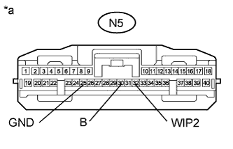
Text in Illustration *a Front view of wire harness connector
(to Driving Support ECU Connector)
-
Disconnect the N5 driving support ECU connector.
-
Measure the voltage according to the value(s) in the table below.
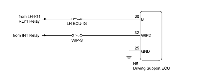
Standard Voltage Tester Connection Condition Specified Condition N5-30 (B) - Body ground Always 11 to 14 V N5-32 (WIP2) - Body ground Engine switch on (IG), windshield wiper switch Hi -
Measure the resistance according to the value(s) in the table below.
Standard Resistance Tester Connection Condition Specified Condition N5-25 (GND) - Body ground Always Below 1 Ω
NG
REPAIR OR REPLACE HARNESS OR CONNECTOR
OK 
PROCEED TO NEXT SUSPECTED AREA SHOWN IN PROBLEM SYMPTOMS TABLE Click here
-