OIL PUMP INSTALLATION

-
INSTALL TIMING CHAIN COVER SUB-ASSEMBLY
-
Remove any old packing material remaining on the sealing surfaces before applying seal packing.
-
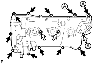
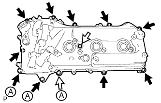
Clean and degrease the contact surfaces of the timing chain cover, cylinder head and cylinder block, and confirm that no oil, moisture or other foreign matter remains on the surfaces.
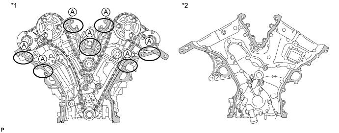
Text in Illustration *1 Cylinder Head and Cylinder Block *2 Timing Chain Cover 
Area to be cleaned and degreased - - Note
Be sure to clean and degrease the contact surfaces, especially the surfaces indicated by A in the illustration.
-
Install a new gasket.
-
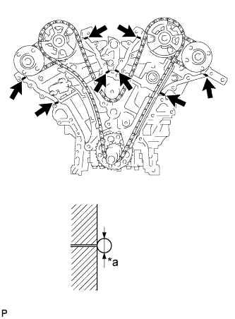
Text in Illustration *a 3.0 mm (0.118 in.) or more Apply seal packing in a continuous line to the engine unit as shown in the illustration.
Seal packing Toyota Genuine Seal Packing Black, Three Bond 1207B or equivalent Seal diameter 3.0 mm (0.118 in.) or more Note
-
If the contact surfaces are wet, wipe them with an oil-free cloth before applying seal packing.
-
Install the chain cover within 3 minutes and tighten the bolts within 15 minutes after applying seal packing.
-
Do not add engine oil for at least 2 hours after installing the chain cover.
-
Do not start the engine for at least 2 hours after installing the chain cover.
-
-
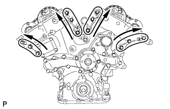
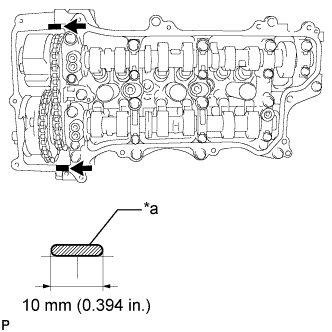
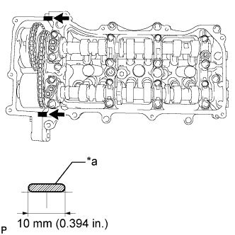
Apply seal packing in a line to the timing chain cover as shown in the following illustration.
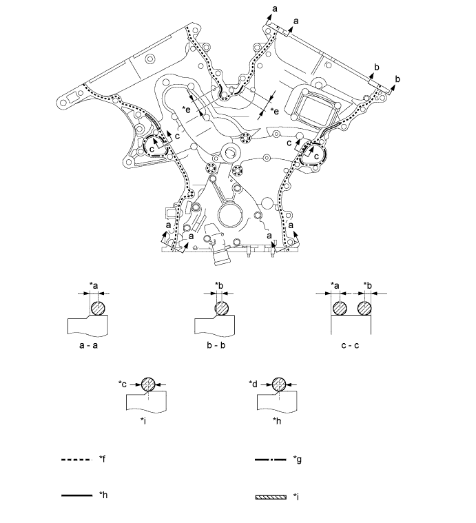
Text in Illustration *a 3.0 to 4.0 mm (0.118 to 0.157 in.) *b 2.0 to 3.0 mm (0.0787 to 0.118 in.) *c 6.0 mm (0.236 in.) or more *d 4.5 mm (0.177 in.) or more *e 20 mm (0.787 in.) *f Dashed line area
(Seal packing: Toyota Genuine Seal Packing Black, Three Bond 1207B or equivalent)
*g Alternate long and short dashed line area
(Seal packing: Toyota Genuine Seal Packing 1282B, Three Bond 1282B or equivalent)
*h Continuous line area
(Seal packing: Toyota Genuine Seal Packing Black, Three Bond 1207B or equivalent)
*i Diagonal line area
(Seal packing: Toyota Genuine Seal Packing Black, Three Bond 1207B or equivalent)
- - Seal Packing Application Chart Area Seal Packing Diameter Application Position from Inside Seal Line Diagonal Line Area 6.0 mm (0.236 in.) or more 3.0 to 4.0 mm (0.118 to 0.158 in.) Continuous Line Area 4.5 mm (0.177 in.) or more 3.0 to 4.0 mm (0.118 to 0.158 in.) Dashed Line Area 3.5 mm (0.138 in.) or more
-
a - a: 3.0 to 4.0 mm (0.118 to 0.158 in.)
-
b - b: 2.0 to 3.0 mm (0.0787 to 0.118 in.)
Alternate Long and Dashed Line Area 3.5 mm (0.138 in.) or more 2.0 to 3.0 mm (0.0787 to 0.118 in.) Seal packing Toyota Genuine Seal Packing Black, Three Bond 1207B or equivalent Toyota Genuine Seal Packing 1282B, Three Bond 1282B or equivalent Note
-
If the contact surfaces are wet, wipe them with an oil-free cloth before applying seal packing.
-
Install the chain cover within 3 minutes and tighten the bolts within 15 minutes after applying seal packing.
-
Do not add the engine oil for at least 2 hours after installing.
-
Do not start the engine for at least 2 hours after installing.
-
-
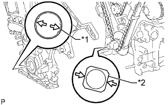
Text in Illustration *1 Drive Rotor Spline *2 Crankshaft Align the oil pump's drive rotor spline and the crankshaft as shown in the illustration. Install the chain cover to the crankshaft.
-
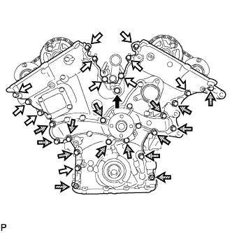
Temporarily tighten the timing chain cover with the 25 bolts and 2 nuts.
Text in Illustration 
Bolt A 
Bolt B 
Nut 
Bolt C Bolt Length Item Specified Condition Bolt A 50 mm (1.97 in.) Bolt B 28 mm (1.102 in.) Bolt C 55 mm (2.17 in.) Note
Make sure that there is no oil on the bolt threads.
-
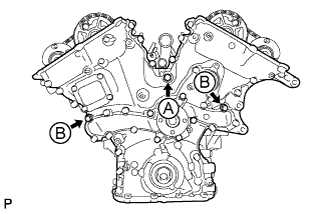
Fully tighten the 3 bolts shown in the illustration.
- Torque:
- for bolt A
- 43 N*m { 438 kgf*cm, 32 ft.*lbf }
- for bolt B
- 21 N*m { 214 kgf*cm, 15 ft.*lbf }
-
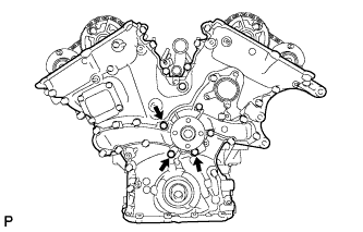
Fully tighten the 3 bolts shown in the illustration.
- Torque:
- 21 N*m { 214 kgf*cm, 15 ft.*lbf }
-
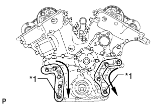
Text in Illustration *1 Nut Fully tighten the 7 bolts and 2 nuts shown in the illustration.
- Torque:
- 21 N*m { 214 kgf*cm, 15 ft.*lbf }
Tech Tips
Tighten the bolts and nuts in order from upper to lower as shown in the illustration.
-
Fully tighten the 12 bolts shown in the illustration.
- Torque:
- 21 N*m { 214 kgf*cm, 15 ft.*lbf }
Tech Tips
Tighten the bolts in order from lower to upper as shown in the illustration.
-
Install the wiring harness clamp bracket with the bolt.
- Torque:
- 10 N*m { 102 kgf*cm, 7 ft.*lbf }
-
-
INSTALL TIMING CHAIN CASE OIL SEAL
-
Apply MP grease to the lip of a new oil seal.
Note
Keep the lip free of foreign matter.
-
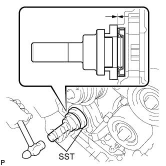
Using SST and a hammer, tap in the oil seal until its surface is flush with the timing chain case edge.
- SST
- 09223-22010
- 09506-35010
Note
-
Keep the lip free of foreign matter.
-
Do not tap the oil seal at an angle.
-
-
INSTALL SPARK PLUG TUBE GASKET
-
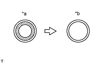
Text in Illustration *a Before cutting off *b After cutting off 
Area to be cut off Using a cutter, cut off the sealing part of the removed plug tube gasket.
-
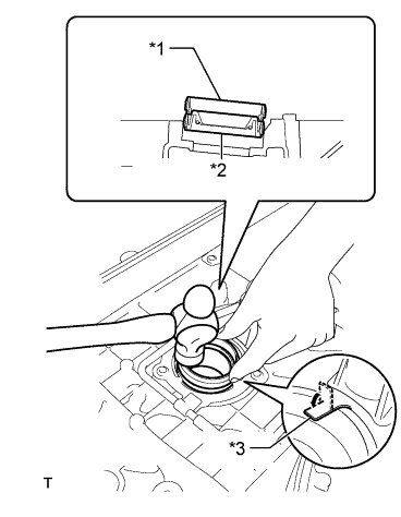
Text in Illustration *1 Plug tube gasket without sealing part *2 New plug tube gasket *3 Claw Using a plug tube gasket which has had the sealing part cut off, uniformly press in a new plug tube gasket all the way.
Note
-
Keep the lip free of foreign matter.
-
Do not tap on the oil seal at an angle.
Tech Tips
If a plug tube gasket that will be used to install a new gasket is deformed, and cannot be positioned on a new gasket, correct the deformation using pliers.
-
-
Return the claws of the ventilation baffle plate to their original positions.
-
-
INSTALL CYLINDER HEAD COVER SUB-ASSEMBLY
-
Text in Illustration *a 2.0 to 3.0 mm Seal Packing Apply seal packing as shown in the illustration.
Seal packing Toyota Genuine Seal Packing Black, Three Bond 1207B or equivalent Note
-
Remove any oil from the contact surface.
-
Install the head cover within 3 minutes after applying seal packing.
-
Do not start the engine for at least 2 hours after installation.
-
-
Install 3 new gaskets to the camshaft bearing caps.
-
Install a new gasket to the head cover.
-
Apply adhesive 1324 to the threads of the 11 cylinder head cover bolts indicated by the black arrows in the illustration.
Text in Illustration Apply adhesive 1324 to these bolts -
Install the head cover with the 14 bolts.
- Torque:
- for bolt A
- 21 N*m { 214 kgf*cm, 15 ft.*lbf }
- for bolts except A
- 10 N*m { 102 kgf*cm, 7 ft.*lbf }
-
-
INSTALL CYLINDER HEAD COVER SUB-ASSEMBLY LH
-
Text in Illustration *a 2.0 to 3.0 mm Seal Packing Apply seal packing as shown in the illustration.
Seal packing Toyota Genuine Seal Packing Black, Three Bond 1207B or equivalent Note
-
Remove any oil from the contact surface.
-
Install the head cover within 3 minutes after applying seal packing.
-
Do not start the engine for at least 2 hours after installation.
-
-
Install 3 new gaskets to the camshaft bearing caps.
-
Install a new gasket to the head cover.
-
Apply adhesive 1324 to the threads of the 11 cylinder head cover bolts indicated by the black arrows in the illustration.
Text in Illustration Apply adhesive 1324 to these bolts -
Install the head cover with the 12 bolts.
- Torque:
- for bolt A
- 21 N*m { 214 kgf*cm, 15 ft.*lbf }
- for bolts except A
- 10 N*m { 102 kgf*cm, 7 ft.*lbf }
-
-
INSTALL FUEL TUBE SUB-ASSEMBLY
-
Install the 2 bolts and fuel tube sub-assembly.
- Torque:
- 10 N*m { 102 kgf*cm, 7 ft.*lbf }
-
-
INSTALL NO. 2 OIL PIPE
-
Make sure that there is no foreign matter on the mesh of the oil control valve filter RH.
Note
Do not touch the mesh when installing the oil control valve filter.
-
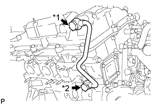
Text in Illustration *1 Oil Pipe Union *2 Oil Check Valve Bolt Install the oil control valve filter RH to the oil pipe union. Install new gaskets and temporarily install the oil pipe (on the head cover side).
-
Install a new gasket and temporarily install the oil pipe (on the cylinder head side) with the oil check valve bolt.
-
Tighten the oil pipe union (on the head cover side).
- Torque:
- 60 N*m { 612 kgf*cm, 44 ft.*lbf }
-
Tighten the oil check valve bolt (on the cylinder head side).
- Torque:
- 60 N*m { 612 kgf*cm, 44 ft.*lbf }
Note
If the link that connects the gaskets is broken, remove the connecting link by using nippers or similar tools.
-
-
INSTALL NO. 1 OIL PIPE
-
Make sure that there is no foreign matter on the mesh of the oil control valve filter LH.
Note
Do not touch the mesh when installing the oil control valve filter.
-
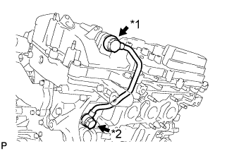
Text in Illustration *1 Oil Pipe Union *2 Oil Check Valve Bolt Install the oil control valve filter LH to the oil pipe union. Install new gaskets and temporarily install the oil pipe (on the head cover side).
-
Install a new gasket and temporarily install the oil pipe (on the cylinder head side) with the oil check valve bolt.
-
Tighten the oil pipe union (on the head cover side).
- Torque:
- 60 N*m { 612 kgf*cm, 44 ft.*lbf }
-
Tighten the oil check valve bolt (on the cylinder head side).
- Torque:
- 60 N*m { 612 kgf*cm, 44 ft.*lbf }
Note
If the link that connects the gaskets is broken, remove the connecting link by using nippers or similar tools.
-
-
INSTALL OIL STRAINER SUB-ASSEMBLY
-
for 2WD:
-
Using an E6 "TORX" socket wrench, install the stud bolts as shown in the illustration.
- Torque:
- 4.0 N*m { 41 kgf*cm, 35 in.*lbf }
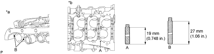
Text in Illustration *a Timing Chain Cover *b Cylinder Block Lower -
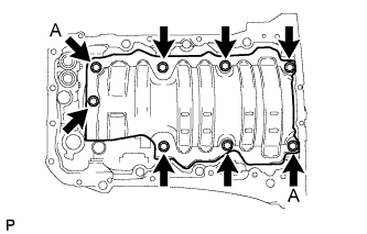
Install the baffle plate with the 8 bolts.
- Torque:
- 10 N*m { 102 kgf*cm, 7 ft.*lbf }
Tech Tips
Temporarily tighten the 8 bolts. Fully tighten 2 bolts A shown in the illustration before tightening the other bolts.
-
Install a new gasket and the oil strainer with the 3 nuts.
- Torque:
- 10 N*m { 102 kgf*cm, 7 ft.*lbf }
-
-
for AWD:
-
Using an E6 "TORX" socket wrench, install the stud bolts as shown in the illustration.
- Torque:
- 4.0 N*m { 41 kgf*cm, 35 in.*lbf }
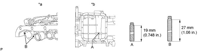
Text in Illustration *a Timing Chain Cover *b Oil Pan Lower -
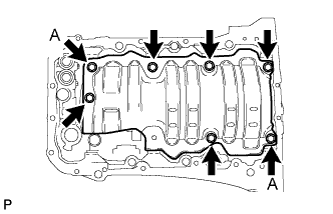
Install the baffle plate with the 7 bolts.
- Torque:
- 10 N*m { 102 kgf*cm, 7 ft.*lbf }
Tech Tips
Temporarily tighten the 7 bolts. Fully tighten 2 bolts A as shown in the illustration before tightening the other bolts.
-
Install a new gasket and the oil strainer with the bolt and 2 nuts.
- Torque:
- 10 N*m { 102 kgf*cm, 7 ft.*lbf }
-
-
Install 2 new O-rings.
-
-
INSTALL OIL PAN SUB-ASSEMBLY
-
When replacing a stud bolt, install it by using an E6 "TORX" socket wrench.
- Torque:
- 4.0 N*m { 41 kgf*cm, 35 in.*lbf }
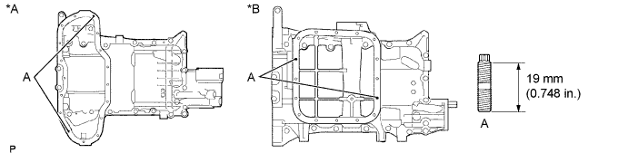
Text in Illustration *A for 2WD *B for AWD -
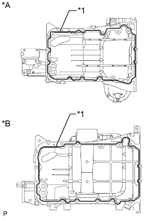
Text in Illustration *A for 2WD *B for AWD *1 Seal Packing Apply seal packing in a continuous line as shown in the illustration.
Seal packing Toyota Genuine Seal Packing Black, Three Bond 1207B or equivalent Seal diameter 3.0 to 4.0 mm (0.118 to 0.156 in.) Note
-
Remove any oil from the contact surface.
-
Install the oil pan within 3 minutes after applying seal packing.
-
Do not start the engine for at least 2 hours after installation.
-
-
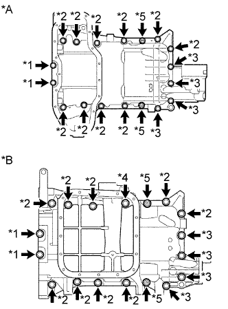
Text in Illustration *A for 2WD *B for AWD *1 Bolt A *2 Bolt B *3 Bolt C *4 Bolt D *5 Nut Install the oil pan with the 16 bolts and 2 nuts.
- Torque:
- for bolt A
- 10 N*m { 102 kgf*cm, 7 ft.*lbf }
- except bolt A
- 21 N*m { 214 kgf*cm, 15 ft.*lbf }
Standard Bolt Item Length Bolt A 16 mm (0.630 in.) Bolt B 25 mm (0.984 in.) Bolt C 45 mm (1.77 in.) Bolt D 93 mm (3.66 in.)
-
-
INSTALL OIL WITH STRAINER PIPE SUB-ASSEMBLY (for AWD)
-
Install a new gasket and the oil with strainer pipe with the 3 nuts.
- Torque:
- 10 N*m { 102 kgf*cm, 7 ft.*lbf }
-
-
INSTALL NO. 2 OIL PAN SUB-ASSEMBLY
-
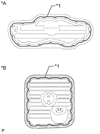
Text in Illustration *A for 2WD *B for AWD *1 Seal Packing Apply seal packing in a continuous line as shown in the illustration.
Seal packing Toyota Genuine Seal Packing Black, Three Bond 1207B or equivalent Seal diameter 4.0 to 6.0 mm (0.156 to 0.236 in.) Note
-
Remove any oil from the contact surface.
-
Install the No. 2 oil pan within 3 minutes after applying seal packing.
-
Do not start the engine for at least 2 hours after installation.
-
-
for 2WD:
-
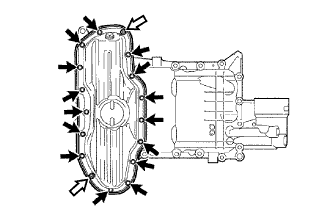
Install the oil pan with the 15 bolts and 2 nuts.
- Torque:
- 10 N*m { 102 kgf*cm, 7 ft.*lbf }
Text in Illustration Bolt Nut
-
-
for AWD:
-
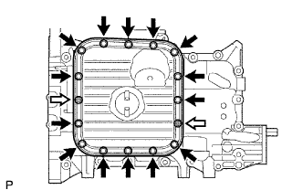
Install the oil pan with the 14 bolts and 2 nuts.
- Torque:
- 10 N*m { 102 kgf*cm, 7 ft.*lbf }
Text in Illustration Bolt Nut
-
-
-
INSTALL CRANKSHAFT PULLEY
-
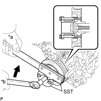
Text in Illustration *a Hold *b Turn Align the pulley set key with the key groove of the pulley, and slide on the pulley.
-
Using SST, install the crankshaft pulley bolt.
- SST
- 09213-70011 ( 09213-70020 )
- 09330-00021
- Torque:
- 250 N*m { 2549 kgf*cm, 184 ft.*lbf }
-
-
INSTALL IGNITION COIL ASSEMBLY
Tech Tips
w/ Canister Pump Module:
Perform "Inspection After Repairs" after replacing the ignition coil Click here.
-
Install the 6 ignition coils with the 6 bolts.
- Torque:
- 10 N*m { 102 kgf*cm, 7 ft.*lbf }
-
Connect the 6 ignition coil connectors.
-
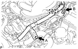
Connect the 2 wire harness brackets with the 2 bolts.
- Torque:
- for bolt A
- 21 N*m { 214 kgf*cm, 15 ft.*lbf }
- for bolt B
- 10 N*m { 102 kgf*cm, 7 ft.*lbf }
-
Connect the wire harness clamp.
-
Connect the wire harness with the 2 nuts.
- Torque:
- 10 N*m { 102 kgf*cm, 7 ft.*lbf }
-
-
INSTALL WATER INLET ASSEMBLY
-
Install a new No. 1 water inlet housing gasket and water outlet pipe O-ring.
-
Install the water inlet assembly with the 4 bolts and nut.
- Torque:
- 10 N*m { 102 kgf*cm, 7 ft.*lbf }
Note
Be careful not to allow the O-ring to get caught between parts.
-
Connect the 5 hoses.
-
-
INSTALL NO. 2 ENGINE COVER
-
Install the No. 2 engine cover with the 3 clips.
-
Connect the clamp.
-
-
INSTALL INJECTOR DRIVER
Note
-
Be careful not to drop or strike the injector driver.
-
The injector driver is grounded at the bolt and nut. To ensure that it is grounded, clean all oil and foreign matter from the installation areas of the injector driver and engine before installing the injector driver.
-
Install the injector driver with the bolt and 2 nuts.
- Torque:
- 10 N*m { 102 kgf*cm, 7 ft.*lbf }
-
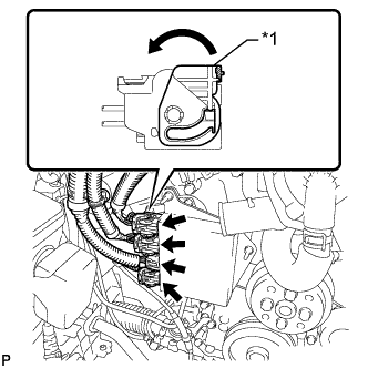
Text in Illustration *1 Lock Lever Connect the 4 connectors to the injector driver. Move the lock levers in the direction indicated by the arrow to lock the 3 connectors.
-
-
INSTALL NO. 1 ENGINE COVER
-
Install the No. 1 engine cover with the 3 clips.
-
-
INSTALL WATER PUMP PULLEY
-
Temporarily install the pulley with the 4 bolts.
-
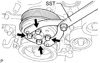
Using SST, hold the pulley and tighten the 4 bolts.
- SST
- 09960-10010 ( 09962-01000, 09963-00700 )
- Torque:
- 21 N*m { 214 kgf*cm, 15 ft.*lbf }
-
-
INSTALL NO. 2 IDLER PULLEY SUB-ASSEMBLY
-
Install the pulley and cover plate with the bolt.
- Torque:
- 43 N*m { 438 kgf*cm, 32 ft.*lbf }
-
-
INSTALL V-RIBBED BELT TENSIONER ASSEMBLY
-
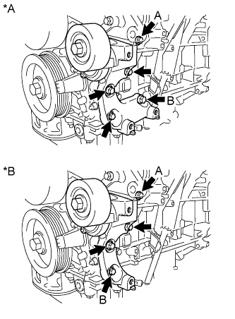
Text in Illustration *A for 2WD *B for AWD Temporarily install the V-ribbed belt tensioner assembly with the bolt A and bolt B.
-
Temporarily install the other bolts.
-
for 2WD:
Tighten the 5 bolts to install the V-ribbed belt tensioner assembly.
- Torque:
- 43 N*m { 439 kgf*cm, 32 ft.*lbf }
-
for AWD:
Tighten the 4 bolts to install the V-ribbed belt tensioner assembly.
- Torque:
- 43 N*m { 439 kgf*cm, 32 ft.*lbf }
-
-
INSTALL FUEL PUMP ASSEMBLY (for High Pressure)
-
INSTALL ENGINE WIRE
-
INSTALL ENGINE ASSEMBLY