CRUISE CONTROL SYSTEM TERMINALS OF ECM

-
CHECK ECM
-
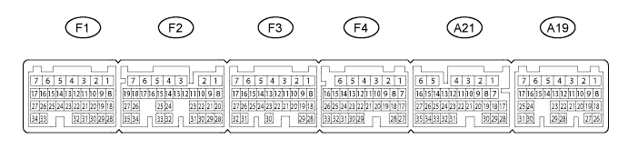
Disconnect the F1, F4, A19 and A21 ECM connectors.
-
Measure the voltage and resistance according to the value(s) in the table below.
Terminal No. (Symbol) Wiring Color Terminal Description Condition Specified Condition A19-7 (BATT) - F4-1 (E1) L - BR Battery (for measuring battery voltage and for ECM memory) Always 11 to 14 V F1-1 (+BM) - F4-1 (E1) P - BR Power source of throttle motor Always 11 to 14 V A19-12 (ST1-) - F4-1 (E1) GR - BR Normally closed switch Engine switch on (IG), Brake pedal depressed Below 1.5 V A19-12 (ST1-) - F4-1 (E1) GR - BR Normally closed switch Engine switch on (IG), Brake pedal released 7.5 to 14 V A19-13 (STP) - F4-1 (E1) R - BR Normally open switch Brake pedal depressed 7.5 to 14 V A19-13 (STP) - F4-1 (E1) R - BR Normally open switch Brake pedal released Below 1.5 V A21-7 (SFTD) - F4-1 (E1) W - BR Down shift switch signal Engine switch on (IG) and shift lever M position 11 to 14 V A21-7 (SFTD) - F4-1 (E1) W - BR Down shift switch signal Engine switch on (IG) and shift lever "-" position (Down shift) Below 1 V A21-7 (SFTD) - F4-1 (E1) W - BR Down shift switch signal Engine switch on (IG) and "-" shift paddle operated and held (down-shift) Below 1 V A21-8 (SFTU) - F4-1 (E1) Y - BR Up shift switch signal Engine switch on (IG) and shift lever M position 11 to 14 V A21-8 (SFTU) - F4-1 (E1) Y - BR Up shift switch signal Engine switch on (IG) and shift lever "+" position (Up shift) Below 1 V A21-8 (SFTU) - F4-1 (E1) Y - BR Up shift switch signal Engine switch on (IG) and "+" shift paddle operated and held (up-shift) Below 1 V A21-15 (CCS) - Body ground B - Body ground Cruise control main switch signal Cruise control main switch on Below 1 Ω A21-15 (CCS) - Body ground B - Body ground Cruise control main switch signal Cruise control main switch off 1 MΩ or higher A21-15 (CCS) - Body ground B - Body ground Cruise control main switch signal +/RES switch is held on 235 to 245 Ω A21-15 (CCS) - Body ground B - Body ground Cruise control main switch signal -/SET switch is held on 617 to 643 Ω A21-15 (CCS) - Body ground B - Body ground Cruise control main switch signal CANCEL switch is held on 1509 to 1571 Ω A21-16 (S) - F4-1 (E1) R - BR M shift position switch signal Engine switch on (IG) and shift lever M position 11 to 14 V A21-16 (S) - F4-1 (E1) R - BR M shift position switch signal Engine switch on (IG) and shift lever except M position Below 1 V If the result is not as specified, there may be a malfunction on the wire harness side.
-