WATER PUMP INSTALLATION

-
INSTALL ENGINE WATER PUMP ASSEMBLY
-
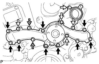
Install a new water pump gasket and the engine water pump assembly with the 16 bolts.
- Torque:
- for bolt A
- 21 N*m { 214 kgf*cm, 15 ft.*lbf }
- for bolt B, C
- 11 N*m { 112 kgf*cm, 8 ft.*lbf }
Text in Illustration 
Bolt A 
Bolt B 
Bolt C Note
-
Be sure to apply adhesive to the 2 bolts labeled C before reusing them, or replace them with new ones if necessary.
Adhesive Toyota Genuine Adhesive 1344, Three Bond 1344 or equivalent -
Make sure that there is no oil on the threads of the bolts labeled A.
Standard length Item Length Bolt A 55 mm (2.17 in.) Bolt B, C 22 mm (0.87 in.)
-
-
INSTALL NO. 2 IDLER PULLEY SUB-ASSEMBLY
-
Install the pulley and cover plate with the bolt.
- Torque:
- 43 N*m { 438 kgf*cm, 32 ft.*lbf }
-
-
INSTALL WATER INLET ASSEMBLY
-
Install a new No. 1 water inlet housing gasket and water outlet pipe O-ring.
-
Install the water inlet assembly with the 4 bolts and nut.
- Torque:
- 10 N*m { 102 kgf*cm, 7 ft.*lbf }
Note
Be careful not to allow the O-ring to get caught between parts.
-
Connect the 5 hoses.
-
-
INSTALL WATER PUMP PULLEY
-
Temporarily install the pulley with the 4 bolts.
-
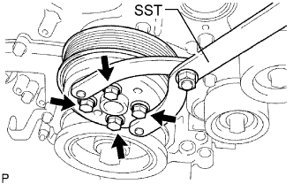
Using SST, hold the pulley and tighten the 4 bolts.
- SST
- 09960-10010 ( 09962-01000, 09963-00700 )
- Torque:
- 21 N*m { 214 kgf*cm, 15 ft.*lbf }
-
-
INSTALL NO. 2 ENGINE COVER
-
Install the No. 2 engine cover with the 3 clips.
-
Connect the clamp.
-
-
INSTALL INJECTOR DRIVER
Note
-
Be careful not to drop or strike the injector driver.
-
The injector driver is grounded at the bolt and nut. To ensure that it is grounded, clean all oil and foreign matter from the installation areas of the injector driver and engine before installing the injector driver.
-
Install the injector driver with the bolt and 2 nuts.
- Torque:
- 10 N*m { 102 kgf*cm, 7 ft.*lbf }
-
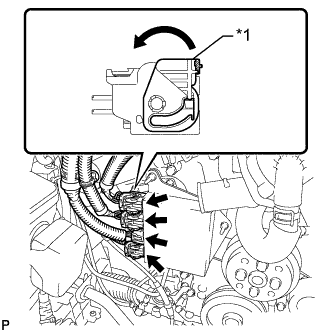
Text in Illustration *1 Lock Lever Connect the 4 connectors to the injector driver. Move the lock levers in the direction indicated by the arrow to lock the 3 connectors.
-
-
INSTALL NO. 1 ENGINE COVER
-
Install the No. 1 engine cover with the 3 clips.
-
-
CONNECT NO. 2 RADIATOR HOSE
-
Connect the No. 2 radiator hose to the water inlet with thermostat sub-assembly and secure it with the clip.
-
-
INSTALL NO. 1 RADIATOR HOSE
-
Install the No. 1 radiator hose to the radiator assembly and secure it with the 2 clamps.
-
-
INSTALL V-RIBBED BELT TENSIONER ASSEMBLY
-
Temporarily install the V-ribbed belt tensioner assembly with the bolt A and bolt B.
-
Temporarily install the other bolts.
-
Tighten the 5 bolts to install the V-ribbed belt tensioner assembly.
- Torque:
- 43 N*m { 439 kgf*cm, 32 ft.*lbf }
-
-
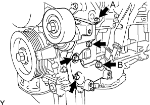
INSTALL COOLER COMPRESSOR ASSEMBLY
-
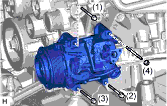
Using an E8 "torx" socket, install the cooler compressor assembly with the stud bolt.
- Torque:
- 10 N*m { 102 kgf*cm, 7 ft.*lbf }
-
Install the cooler compressor assembly with the 3 bolts and nut.
- Torque:
- for bolt
- 25 N*m { 250 kgf*cm, 18 ft.*lbf }
- for nut
- 25 N*m { 250 kgf*cm, 18 ft.*lbf }
Note
Tighten the bolts in the order shown in the illustration to install the cooler compressor assembly.
-
-
CONNECT NO. 1 COOLER REFRIGERANT DISCHARGE HOSE
-
Remove the attached vinyl tape from the No. 1 cooler refrigerant discharge hose.
-
Apply sufficient compressor oil (ND-OIL 8) to a new O-ring and the fitting surface of the cooler compressor assembly.
Compressor oil ND-OIL 8 or equivalent -
Install the O-ring on the No. 1 cooler refrigerant discharge hose.
-
Install the No. 1 cooler refrigerant discharge hose on the cooler compressor assembly with the bolt.
- Torque:
- 9.8 N*m { 100 kgf*cm, 87 in.*lbf }
-
-
CONNECT SUCTION HOSE
-
Remove the attached vinyl tape from the suction hose.
-
Apply sufficient compressor oil (ND-OIL 8) to a new O-ring and the fitting surface of the cooler compressor assembly.
Compressor oil ND-OIL 8 or equivalent -
Install the O-ring on the suction hose.
-
Install the suction hose on the cooler compressor assembly with the bolt.
- Torque:
- 9.8 N*m { 100 kgf*cm, 87 in.*lbf }
-
-
INSTALL FAN AND GENERATOR V BELT
-
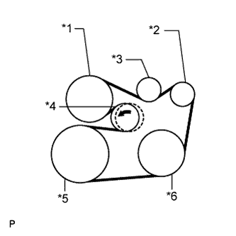
Text in Illustration *1 Engine Water Pump *2 Generator *3 Idler *4 Tensioner *5 Crankshaft *6 A/C Compressor Set the V belt onto every part.
-
While turning the belt tensioner counterclockwise, remove the bar.
Note
-
Put the backside of the V belt on the tensioner pulley and idler pulley.
-
Check that the V belt is properly set to each pulley.
-
-
If it is difficult to install the V belt, perform the following procedure.
-
Put the V belt on every part except the tensioner pulley.
-
Put the V belt on the tensioner pulley while turning the belt tensioner counterclockwise.
Note
-
Put the backside of the V belt on the tensioner pulley and idler pulley.
-
Check that the V belt is properly set to each pulley.
-
-
-
Check that the belt fits properly in the ribbed grooves.
Tech Tips
Make sure to check by hand that the belt has not slipped out of the grooves on the bottom of the pulley.
-
-
ADD ENGINE COOLANT
-
Tighten the radiator drain cock plug by hand.
-
Tighten the 2 cylinder block drain cock plugs.
- Torque:
- 13 N*m { 130 kgf*cm, 9 ft.*lbf }
-
Add TOYOTA Super Long Life Coolant (SLLC) to the water outlet sub-assembly opening.
Standard Capacity Item Specified Condition for LHD 10.9 liters (11.5 US qts, 9.6 Imp. qts) for RHD 11.0 liters (11.6 US qts, 9.7 Imp. qts) Tech Tips
TOYOTA vehicles are filled with TOYOTA SLLC at the factory. In order to avoid damage to the engine cooling system and other technical problems, only use TOYOTA SLLC or similar high quality ethylene glycol based non-silicate, non-amine, non-nitrite, non-borate coolant with long-life hybrid organic acid technology (coolant with long-life hybrid organic acid technology is a combination of low phosphates and organic acids).
-
Slowly pour coolant into the radiator reservoir tank until it reaches the full line.
-
Press the No. 1 and No. 2 radiator hoses several times by hand, and then check the level of the coolant.
If the coolant level is low, add coolant.
-
Install the radiator cap.
-
Bleed air from the cooling system.
Note
Before starting the engine to warm up the engine, turn the A/C switch off.
-
Warm up the engine until the thermostat opens. While the thermostat is open, circulate the coolant for several minutes.
CAUTION:
When pressing the radiator hoses:
-
Wear protective gloves.
-
Be careful as the radiator hoses are hot.
-
Keep your hands away from the radiator fans.
Tech Tips
The thermostat open timing can be confirmed by pressing the No. 1 radiator hose by hand, and checking when the engine coolant starts to flow inside the hose.
-
-
Maintain the engine speed at 2000 to 2500 rpm.
-
Press the No. 1 and No. 2 radiator hoses several times by hand to bleed air.
CAUTION:
When pressing the radiator hoses:
-
Wear protective gloves.
-
Be careful as the radiator hoses are hot.
-
Keep your hands away from the radiator fans.
-
-
-
Stop the engine, and wait until the engine coolant cools down to ambient temperature.
CAUTION:
Do not remove the radiator cap while the engine and radiator are still hot. Pressurized, hot engine coolant and steam may be released and cause serious burns.
-
Check the coolant level in the radiator reservoir tank.
If the coolant level is low, add SLLC to the radiator reservoir tank full line.
-
-
CHARGE REFRIGERANT
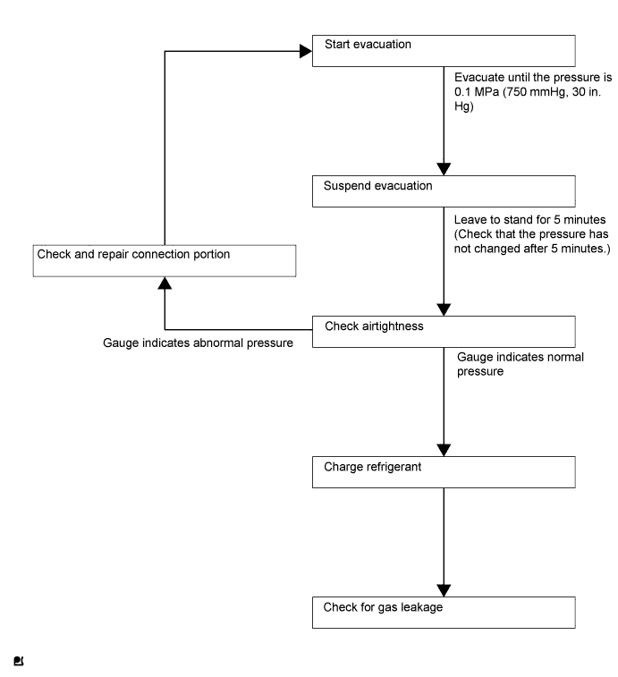
Tech Tips
Charge refrigerant in accordance with the equipment manual.
-
Perform vacuum purging using a vacuum pump.
-
Charge refrigerant HFC-134a (R134a).
- SST
- 09985-20010 ( 09985-02130, 09985-02150, 09985-02090, 09985-02110, 09985-02010, 09985-02050, 09985-02060, 09985-02070 )
Standard 500 +/-50 g (17.64 +/-1.76 oz) 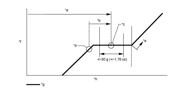
Text in Illustration *a Amount to be charged *b Charge 100 g (3.53 oz) *c Mean value in proper range *d Point where bubbles disappear *e Overcharged *f Pressure *g Sub-cool system *h Refrigerant amount Note
-
Do not operate the cooler compressor before charging refrigerant as the cooler compressor will not work properly without any refrigerant, and will overheat.
-
The system may need to be charged with approximately 100 g (3.53 oz) of refrigerant after bubbles disappear. The refrigerant amount should be checked by measuring its quantity, and not with the sight glass.
-
-
INSPECT FOR COOLANT LEAK
CAUTION:
Do not remove the radiator cap while the engine and radiator are still hot. Pressurized hot engine coolant and steam may be released and cause serious burns.
Note
Before performing each inspection, turn the A/C switch off.
-
Fill the radiator with coolant and attach a radiator cap tester.
-
Warm up the engine.
-
Using a radiator cap tester, increase the pressure inside the radiator to 137 kPa (1.4 kgf/cm2, 20 psi), and check that the pressure does not drop.
If the pressure drops, check the hoses, radiator and water pump for leaks. If no external leaks are found, check the heater core, cylinder block and cylinder head.
-
-
WARM UP ENGINE
-
Warm up the engine at less than 1640 rpm for 2 minutes or more after charging the refrigerant.
Note
Be sure to warm up the compressor by turning the A/C switch on after removing and installing the cooler refrigerant lines (including the compressor) to prevent damage to the compressor.
-
-
INSPECT FOR REFRIGERANT LEAK
-
After recharging the refrigerant, check for refrigerant gas leakage using a halogen leak detector.
-
Perform the operation observing the following instructions:
-
Stop the engine.
-
Secure good ventilation (the halogen leak detector may react to volatile gases other than refrigerant, such as evaporated gasoline or exhaust gas).
-
Repeat the test 2 or 3 times.
-
Make sure that some refrigerant remains in the refrigeration system.
Tech Tips
When the compressor is off: approximately 392 to 588 kPa (4.0 to 6.0 kgf/cm2, 57 to 85 psi).
-
-
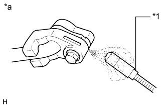
Text in Illustration *1 Halogen Leak Detector *a Check for Leakage Using a halogen leak detector, check the refrigerant line for leakage.
-
If a gas leak is not detected from the drain hose, remove the blower motor control (blower resistor) from the cooling unit. Insert the halogen leak detector sensor into the unit and check for gas leakage.
-
Disconnect the pressure switch connector and wait for approximately 20 minutes. Bring the halogen leak detector close to the pressure switch and check for gas leakage.
-
-
-
INSTALL REAR ENGINE UNDER COVER LH
-
Install the rear engine under cover LH with the screw.
-
-
INSTALL ENGINE UNDER COVER
-
Install the engine under cover with the 13 screws and 3 clips.
-
-
INSTALL NO. 1 AIR CLEANER INLET
-
Install the No. 1 air cleaner inlet with the bolt.
- Torque:
- 5.0 N*m { 51 kgf*cm, 44 in.*lbf }
-
-
INSTALL COOL AIR INTAKE DUCT SEAL
-
Install the cool air intake duct seal with the 7 clips.
-
-
INSTALL ENGINE ROOM SIDE COVER
-
Install the engine room side cover with the 4 clips.
-
-
INSTALL V-BANK COVER SUB-ASSEMBLY
-
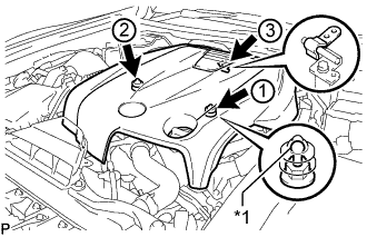
Text in Illustration *1 Tip (Round Portion) Attach the 3 clips in the order shown in the illustration to install the V-bank cover.
Note
-
Securely attach the clips.
-
If the clips are forcibly attached or struck with an object, they may be damaged.
-
Do not apply any oil to the tips (round portions).
-
-