INTAKE MANIFOLD INSTALLATION

-
INSTALL STUD BOLT
Note
If a stud bolt is deformed or its threads are damaged, replace it.
-
Using an E6 "TORX" socket wrench, install the stud bolts.
- Torque:
- 4.0 N*m { 41 kgf*cm, 35 in.*lbf }
-
-
INSTALL INTAKE MANIFOLD
-
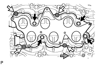
Install 2 new gaskets and the intake manifold with the 4 bolts and 4 nuts.
- Torque:
- 21 N*m { 214 kgf*cm, 15 ft.*lbf }
Text in Illustration 
Bolt 
Nut 
Front -
Connect the intake air control valve actuator connector.
-
w/ Swirl Control Valve Position Sensor:
Connect the swirl control valve position sensor connector.
-
-
INSTALL INTAKE AIR SURGE TANK ASSEMBLY
Note
Do not apply oil to the bolts for the parts listed below:
Part Intake air surge tank assembly and intake manifold Surge tank stay and intake air surge tank assembly
-
Install 3 new gaskets to the intake air surge tank assembly.
-
w/ Cold Start Fuel Injector:
Attach the fuel tube sub-assembly.
-
w/ Swirl Control Valve Position Sensor:
Attach the wire harness clamp.
-
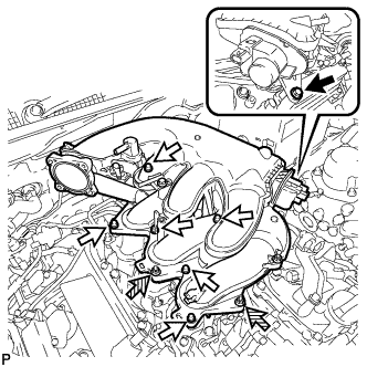
Using a 5 mm long socket hexagon wrench, install the intake air surge tank assembly with the 6 bolts B.
- Torque:
- 18 N*m { 184 kgf*cm, 13 ft.*lbf }
Text in Illustration Bolt A Bolt B Nut -
Install the 2 nuts.
- Torque:
- 16 N*m { 163 kgf*cm, 12 ft.*lbf }
-
Install bolt A.
- Torque:
- 21 N*m { 214 kgf*cm, 15 ft.*lbf }
-
Install the No. 2 surge tank stay with the bolt.
- Torque:
- 21 N*m { 214 kgf*cm, 15 ft.*lbf }
-
Install the No. 3 water by-pass pipe with the bolt.
- Torque:
- 10 N*m { 102 kgf*cm, 7 ft.*lbf }
-
Connect the PCV hose.
-
for LHD:
Connect the connector, union to check valve hose, water by-pass hose and 3 wire harness clamps.
-
for RHD:
Connect the connector, union to check valve hose, water by-pass hose and 4 wire harness clamps.
-
w/ Cold Start Fuel Injector:
Install the cold start fuel injector Click here
-
-
INSTALL PURGE VSV
-
Install the purge VSV with the bolt.
- Torque:
- 18 N*m { 184 kgf*cm, 13 ft.*lbf }
-
Connect the 2 purge line hoses.
-
Connect the purge VSV connector.
-
-
INSTALL THROTTLE BODY WITH MOTOR ASSEMBLY
-
INSTALL COWL TOP VENTILATOR LOUVER SUB-ASSEMBLY
-
CONNECT CABLE TO NEGATIVE BATTERY TERMINAL
Note
When disconnecting the cable, some systems need to be initialized after the cable is reconnected Click here.