INTAKE MANIFOLD INSTALLATION

-
INSTALL STUD BOLT
Note
If a stud bolt is deformed or its threads are damaged, replace it.
-
Using an E6 "TORX" socket wrench, install the stud bolts.
- Torque:
- 4.0 N*m { 41 kgf*cm, 35 in.*lbf }
-
-
INSTALL INTAKE MANIFOLD
-
Install 2 new gaskets and the intake manifold with the 4 bolts and 4 nuts.
- Torque:
- 21 N*m { 214 kgf*cm, 15 ft.*lbf }
-
-
INSTALL FUEL DELIVERY PIPE SUB-ASSEMBLY
-
Install the 4 delivery pipe spacers to the intake manifold.
-
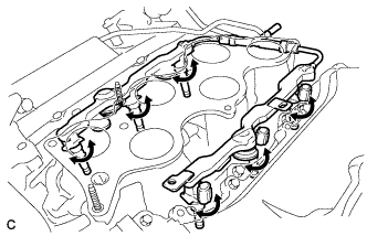
Install the delivery pipe sub-assembly (with injector) to the intake manifold.
Note
When the injector does not rotate smoothly, the O-ring may be pinched. Remove the injector and install a new O-ring to the injector.
Text in Illustration 
Turn -
Install the fuel injector assembly to the fuel delivery pipe sub-assemblies with the 4 bolts.
- Torque:
- 17 N*m { 173 kgf*cm, 13 ft.*lbf }
-
Connect the 6 injector connectors and 2 clamps.
-
Connect the No. 2 fuel tube sub-assembly to the fuel delivery pipe sub-assembly Click here.
-
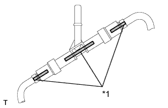
Text in Illustration *1 Mark After connecting the fuel tube, align the paint marks on the delivery pipe.
-
-
INSTALL INTAKE AIR SURGE TANK ASSEMBLY
Note
Do not apply oil to the bolts for the parts listed below:
Part Intake air surge tank assembly and intake manifold Surge tank stay and intake air surge tank assembly
-
Install a new gasket to the intake air surge tank assembly.
-
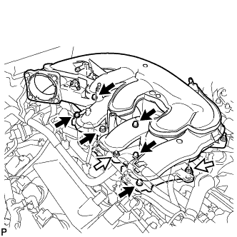
Using a 5 mm long hexagon socket wrench, install the 6 bolts.
Text in Illustration Bolt 
Nut - Torque:
- 18 N*m { 184 kgf*cm, 13 ft.*lbf }
-
Install the intake air surge tank assembly with the 2 nuts.
- Torque:
- 16 N*m { 163 kgf*cm, 12 ft.*lbf }
-
Install the No. 2 surge tank stay with the bolt.
- Torque:
- 21 N*m { 214 kgf*cm, 15 ft.*lbf }
-
Install the No. 3 water by-pass pipe with the bolt.
- Torque:
- 10 N*m { 102 kgf*cm, 7 ft.*lbf }
-
for LHD:
Connect the 4 wire harness clamps.
-
for RHD:
Connect the 5 wire harness clamps.
-
Connect the PCV hose, union to check valve hose and water by-pass hose.
-
-
INSTALL PURGE VSV
-
Install the purge VSV with the bolt.
- Torque:
- 18 N*m { 184 kgf*cm, 13 ft.*lbf }
-
Connect the 2 purge line hoses.
-
Connect the purge VSV connector.
-
-
INSTALL THROTTLE BODY WITH MOTOR ASSEMBLY
-
INSTALL COWL TOP VENTILATOR LOUVER SUB-ASSEMBLY
-
CONNECT CABLE TO NEGATIVE BATTERY TERMINAL
Note
When disconnecting the cable, some systems need to be initialized after the cable is reconnected Click here.
-
INSPECT FOR FUEL LEAK
-
Connect the GTS to the DLC3.
-
Turn the engine switch on (IG).
Note
Do not start the engine.
-
Turn the GTS on.
-
Enter the following menus: Powertrain / Engine and ECT / Active Test / Control the Fuel Pump / Speed.
-
-
Check the fuel pump operation.
-
Check for pressure in the fuel inlet tube from the fuel line. Check that sound of fuel flowing in the fuel tank can be heard.
If no sound can be heard, check the integration relay, fuel pump, ECM and wiring connector.
-
-
Inspect for fuel leaks.
-
Check that there are no fuel leaks anywhere on the system after performing maintenance.
If there is a fuel leak, repair or replace parts as necessary.
-
-