COOLING FAN MOTOR INSTALLATION

-
INSTALL NO. 2 COOLING FAN MOTOR
-
Install the No. 2 cooling fan motor with the 3 screws.
- Torque:
- for 160W+100W Type
- 2.6 N*m { 26 kgf*cm, 23 in.*lbf }
- for 200W+200W Type
- 3.9 N*m { 40 kgf*cm, 34 in.*lbf }
-
-
INSTALL COOLING FAN MOTOR
-
Install the cooling fan motor with the 3 screws.
- Torque:
- 3.9 N*m { 40 kgf*cm, 34 in.*lbf }
-
-
INSTALL NO. 2 FAN
-
Install the No. 2 fan with the nut.
- Torque:
- 6.3 N*m { 64 kgf*cm, 56 in.*lbf }
-
-
INSTALL FAN
-
Install the fan with the nut.
- Torque:
- 6.3 N*m { 64 kgf*cm, 56 in.*lbf }
-
-
INSTALL COOLING FAN ECU
-
Install the cooling fan ECU with the 2 screws.
- Torque:
- 2.6 N*m { 26 kgf*cm, 23 in.*lbf }
-
Connect the 2 connectors and 3 clamps.
-
-
INSTALL FAN SHROUD
-
Attach the 2 claws on the lower part of the fan shroud to the radiator.
-
Attach the claw on the upper part of the fan shroud, and then install the fan shroud to the radiator with the 2 bolts.
- Torque:
- 7.1 N*m { 72 kgf*cm, 63 in.*lbf }
-
-
CONNECT NO. 2 OIL COOLER OUTLET HOSE (w/ Transmission Oil Cooler)
-
Attach the flexible hose clamp.
-
-
INSTALL ENGINE ROOM ECU OUTLET DUCT
-
Install the engine room ECU outlet duct to the engine room ECU box.
-
-
CONNECT NO. 2 ENGINE ROOM WIRE
-
Connect the 6 wire harness clamps, connector and No. 2 engine room wire.
-
-
INSTALL RADIATOR RESERVOIR TANK
-
Install the radiator reservoir tank with the 2 bolts.
- Torque:
- 5.0 N*m { 51 kgf*cm, 44 in.*lbf }
-
Connect the wire harness clamp.
-
Connect the radiator reservoir tank hose to water inlet assembly with the hose clamp.
-
-
INSTALL NO. 1 RADIATOR HOSE
-
Install the No. 1 radiator hose to the radiator assembly and secure it with the 2 clamps.
-
-
INSTALL AIR CLEANER CAP WITH AIR CLEANER HOSE
-
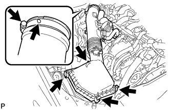
Install the air cleaner cap with air cleaner hose assembly with the 4 clamps and hose clamp.
- Torque:
- 4.0 N*m { 41 kgf*cm, 35 in.*lbf }
Tech Tips
Fit the protrusion on the air cleaner hose into the hole of the hose clamp on the throttle valve side.
-
Connect the VSV hose to the air cleaner hose.
-
for RHD:
Connect the union to check valve hose.
-
Connect the mass air flow meter connector and clamp to the air cleaner.
-
-
ADD ENGINE COOLANT
-
Tighten the radiator drain cock plug by hand.
-
Tighten the 2 cylinder block drain cock plugs.
- Torque:
- 13 N*m { 130 kgf*cm, 9 ft.*lbf }
-
Add TOYOTA Super Long Life Coolant (SLLC) to the water outlet sub-assembly opening.
Standard Capacity Item Specified Condition w/o Transmission Oil Cooler 9.7 liters (10.3 US qts, 8.5 Imp. qts) w/ Transmission Oil Cooler 10.0 liters (10.6 US qts, 8.8 Imp. qts) Tech Tips
TOYOTA vehicles are filled with TOYOTA SLLC at the factory. In order to avoid damage to the engine cooling system and other technical problems, only use TOYOTA SLLC or similar high quality ethylene glycol based non-silicate, non-amine, non-nitrite, non-borate coolant with long-life hybrid organic acid technology (coolant with long-life hybrid organic acid technology is a combination of low phosphates and organic acids).
-
Slowly pour coolant into the radiator reservoir tank until it reaches the full line.
-
Press the No. 1 and No. 2 radiator hoses several times by hand, and then check the level of the coolant.
If the coolant level is low, add coolant.
-
Install the radiator cap.
-
Bleed air from the cooling system.
Note
Before starting the engine to warm up the engine, turn the A/C switch off.
-
Warm up the engine until the thermostat opens. While the thermostat is open, circulate the coolant for several minutes.
CAUTION:
When pressing the radiator hoses:
-
Wear protective gloves.
-
Be careful as the radiator hoses are hot.
-
Keep your hands away from the radiator fans.
Tech Tips
The thermostat open timing can be confirmed by pressing the No. 1 radiator hose by hand, and checking when the engine coolant starts to flow inside the hose.
-
-
Maintain the engine speed at 2000 to 2500 rpm.
-
Press the No. 1 and No. 2 radiator hoses several times by hand to bleed air.
CAUTION:
When pressing the radiator hoses:
-
Wear protective gloves.
-
Be careful as the radiator hoses are hot.
-
Keep your hands away from the radiator fans.
-
-
-
Stop the engine, and wait until the engine coolant cools down to ambient temperature.
CAUTION:
Do not remove the radiator cap while the engine and radiator are still hot. Pressurized, hot engine coolant and steam may be released and cause serious burns.
-
Check the coolant level in the radiator reservoir tank.
If the coolant level is low, add SLLC to the radiator reservoir tank full line.
-
-
INSPECT FOR COOLANT LEAK
CAUTION:
Do not remove the radiator cap while the engine and radiator are still hot. Pressurized hot engine coolant and steam may be released and cause serious burns.
Note
Before performing each inspection, turn the A/C switch off.
-
Fill the radiator with coolant and attach a radiator cap tester.
-
Warm up the engine.
-
Using a radiator cap tester, increase the pressure inside the radiator to 137 kPa (1.4 kgf/cm2, 20 psi), and check that the pressure does not drop.
If the pressure drops, check the hoses, radiator and water pump for leaks. If no external leaks are found, check the heater core, cylinder block and cylinder head.
-
-
INSTALL NO. 1 AIR CLEANER INLET
-
Install the No. 1 air cleaner inlet with the bolt.
- Torque:
- 5.0 N*m { 51 kgf*cm, 44 in.*lbf }
-
-
INSTALL V-BANK COVER SUB-ASSEMBLY
-
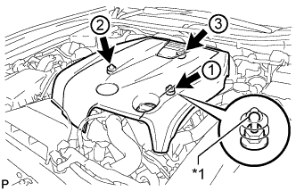
Text in Illustration *1 Tip (Round Portion) Attach the 3 clips in the order shown in the illustration to install the V-bank cover.
Note
-
Securely attach the clips.
-
If the clips are forcibly attached or struck with an object, they may be damaged.
-
Do not apply any oil to the tips (round portions).
-
-
-
INSTALL COOL AIR INTAKE DUCT SEAL
-
Install the cool air intake duct seal with the 7 clips.
-
-
INSTALL ENGINE ROOM SIDE COVER
-
Install the engine room side cover with the 4 clips.
-