WATER PUMP REMOVAL

-
REMOVE V-BANK COVER SUB-ASSEMBLY
-
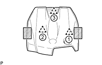
Place both hands on the sides of the cover as shown in the illustration, lift the cover to detach the 2 clips near the front in the order shown in the illustration, and then lift the cover further to detach the rear clip and remove the cover.
Text in Illustration 
Areas to place hands when lifting cover Note
If the cover is lifted rearward or forward and to the right or left at the same time, the cover maybe damaged.
-
-
REMOVE ENGINE ROOM SIDE COVER
-
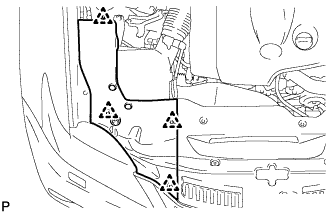
Remove the 4 clips and engine room side cover.
-
-
REMOVE COOL AIR INTAKE DUCT SEAL
-
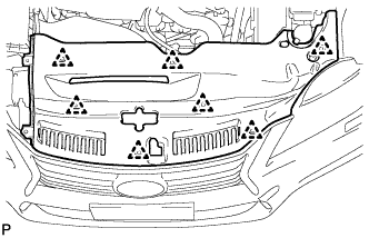
Remove the 7 clips and cool air intake duct seal.
-
-
REMOVE NO. 1 AIR CLEANER INLET
-
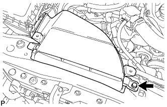
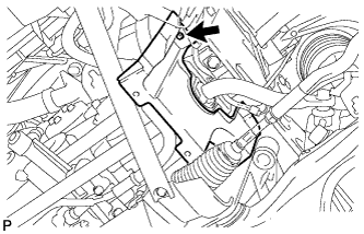
Remove the bolt and No. 1 air cleaner inlet.
-
-
RECOVER REFRIGERANT FROM REFRIGERATION SYSTEM
-
for HFC-134a (R134a):
-
for HFO-1234yf (R1234yf):
-
-
DRAIN ENGINE COOLANT
-
Loosen the radiator drain cock plug and drain the coolant.
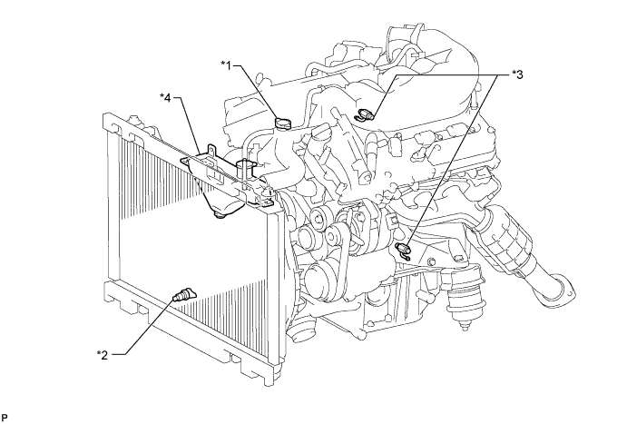
Text in Illustration *1 Radiator Cap *2 Radiator Drain Cock Plug *3 Cylinder Block Drain Cock Plug *4 Radiator Reservoir Tank CAUTION:
Do not remove the radiator cap, cylinder block drain cock plugs and radiator drain cock plug while the engine and radiator are still hot. Pressurized, hot engine coolant and steam may be released and cause serious burns.
Tech Tips
Collect the coolant in a container and dispose of it according to the local regulations.
-
Remove the radiator cap.
-
Loosen the 2 cylinder block drain cock plugs.
-
-
REMOVE FAN AND GENERATOR V BELT
-
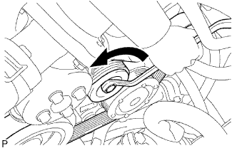
While releasing the belt tension by turning the belt tensioner counterclockwise, remove the V belt from the belt tensioner.
-
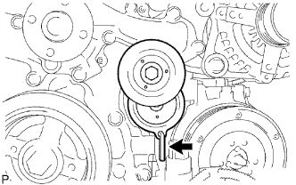
While turning the belt tensioner counterclockwise, align its holes, and then insert the 5 mm bi-hexagon wrench into the holes to secure the belt tensioner.
-
-
REMOVE ENGINE UNDER COVER
-
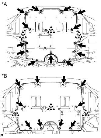
Text in Illustration *A for 2WD *B for AWD for 2WD:
Remove the 13 screws, 3 clips and engine under cover.
-
for AWD:
Remove the 10 screws, 3 clips and engine under cover.
-
-
REMOVE REAR ENGINE UNDER COVER LH (for 2WD)
-
Remove the screw and rear engine under cover LH.
-
-
DRAIN ENGINE OIL (for AWD)
-
Remove the oil filler cap.
-
Remove the drain plug and gasket.
-
Install a new gasket and the drain plug.
- Torque:
- 40 N*m { 408 kgf*cm, 30 ft.*lbf }
-
-
REMOVE OIL FILTER BRACKET (for AWD)
-
Remove the bolt, nut and oil filter bracket.
-
-
REMOVE OIL FILTER BRACKET SUB-ASSEMBLY (for AWD)
-
Detach the 2 clamps, and disconnect the connector and wire harness.
-
Remove the bolt, 2 nuts and oil filter bracket.
Tech Tips
Collect the engine oil in a container.
-
-
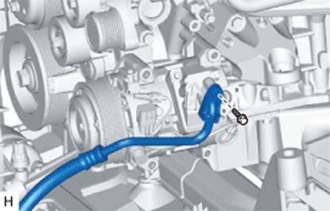
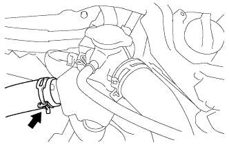
DISCONNECT SUCTION HOSE
-
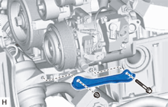
Remove the bolt and disconnect the suction hose from the cooler compressor assembly.
-
Remove the O-ring from the suction hose.
Note
Seal the openings of the disconnected parts using vinyl tape to prevent moisture and foreign matter from entering them.
-
-
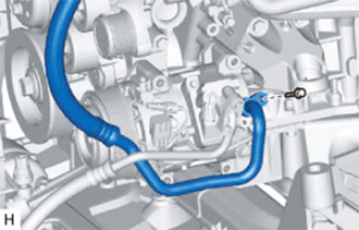
DISCONNECT NO. 1 COOLER REFRIGERANT DISCHARGE HOSE
-
Remove the bolt and disconnect the No. 1 cooler refrigerant discharge hose from the cooler compressor assembly.
-
Remove the O-ring from the No. 1 cooler refrigerant discharge hose.
Note
Seal the openings of the disconnected parts using vinyl tape to prevent moisture and foreign matter from entering them.
-
-
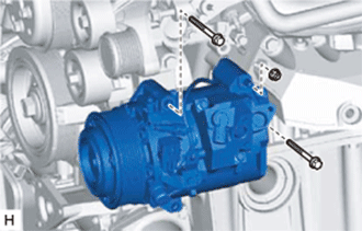
REMOVE COOLER COMPRESSOR ASSEMBLY (for 2WD)
-
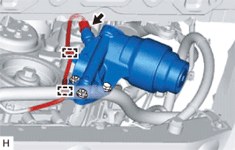
Disconnect the connector.
-
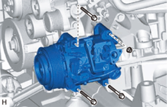
Remove the 3 bolts and nut.
-
Using an E8 "torx" socket, remove the stud bolt and cooler compressor assembly.
-
-
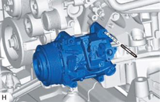
REMOVE COOLER COMPRESSOR ASSEMBLY (for AWD)
-
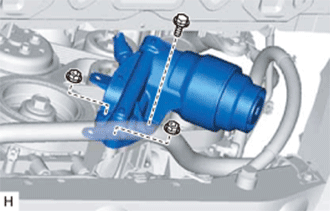
Disconnect the magnetic clutch connector.
-
Remove the 2 bolts, nut and oil filter bracket.
-
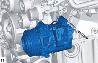
Using an E8 "torx" socket, remove the stud bolt and cooler compressor assembly.
-
-
REMOVE V-RIBBED BELT TENSIONER ASSEMBLY
-
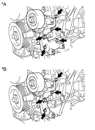
Text in Illustration *A for 2WD *B for AWD for 2WD:
Remove the 5 bolts, then remove the V-ribbed belt tensioner assembly.
-
for AWD:
Remove the 4 bolts, then remove the V-ribbed belt tensioner assembly.
-
-
REMOVE NO. 1 RADIATOR HOSE
-

Remove the No. 1 radiator hose.
-
-
DISCONNECT NO. 2 RADIATOR HOSE
-
Disconnect the No. 2 radiator hose from the water inlet with thermostat sub-assembly.
-
-
REMOVE NO. 1 ENGINE COVER
-
Remove the 3 clips and No. 1 engine cover.
-
-
REMOVE INJECTOR DRIVER
-
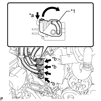
Text in Illustration *1 Lock Lever *a Release *b Lock with Connector Move the lock levers in the direction indicated by the arrow to release the 3 connector locks. Disconnect the 4 connectors from the injector driver.
-
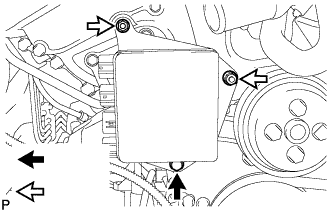
Remove the bolt, 2 nuts and injector driver.
Note
Be careful not to drop or strike the injector driver.
-
-
REMOVE NO. 2 ENGINE COVER
-
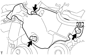
Remove the 3 clips and clamp, then remove the No. 2 engine cover.
-
-
REMOVE WATER PUMP PULLEY
-
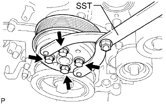
Using SST, hold the water pump pulley.
- SST
- 09960-10010 ( 09962-01000, 09963-00700 )
-
Remove the 4 bolts and water pump pulley.
-
-
REMOVE WATER INLET ASSEMBLY
-

Disconnect the 5 hoses.
-

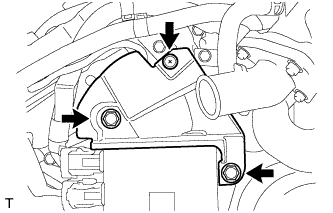
Remove the 4 bolts, nut and water inlet assembly.
Text in Illustration 
Bolt 
Nut -

Text in Illustration *1 No. 1 Water Inlet Housing Gasket *2 Water Outlet Pipe O-ring Remove the No. 1 water inlet housing gasket and water outlet pipe O-ring.
-
-
REMOVE NO. 2 IDLER PULLEY SUB-ASSEMBLY
-
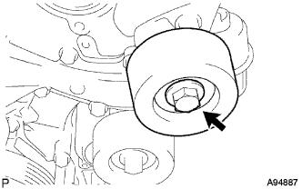
Remove the bolt, No. 2 idler pulley cover plate and No. 2 idler pulley sub-assembly.
-
-
REMOVE ENGINE WATER PUMP ASSEMBLY
-

Remove the 16 bolts, engine water pump assembly and water pump gasket.
-