FUEL SENDER GAUGE ASSEMBLY (w/o Canister Pump Module) INSTALLATION

-
INSTALL NO. 2 FUEL SENDER GAUGE ASSEMBLY
-
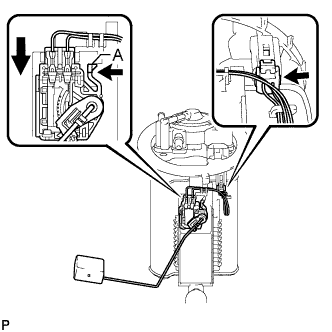
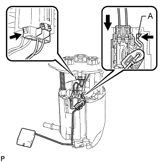
Slide the No. 2 fuel sender gauge assembly downwards and attach the claw labeled A to install the No. 2 fuel sender gauge assembly.
-
Connect the fuel sender gauge connector.
Note
Do not touch the resistance plate or contacts of the No. 2 fuel sender gauge assembly.
-
-
INSTALL FUEL TANK VENT TUBE ASSEMBLY
-
Install a new fuel suction tube set gasket to the fuel tank assembly.
-
Connect the fuel return vent tube sub-assembly and set the fuel tank vent tube assembly on the fuel tank assembly.
Note
-
Do not bend the arm of the No. 2 fuel sender gauge assembly.
-
When connecting the fuel tube connector, do not excessively pull on the fuel return vent tube sub-assembly.
-
-
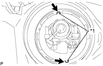
Text in Illustration *1 Protrusion 
Hole Align the protrusions of the fuel tank vent tube assembly with the holes in the fuel tank assembly.
-
While pressing down on the fuel tank vent tube assembly with your hand, temporarily install the fuel pump gauge retainer.
-
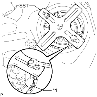
Text in Illustration *1 Insertion Point Set the 2 claws and plate of SST on the fuel pump gauge retainer.
Note
Securely insert the ends of SST into the insertion points in the fuel pump gauge retainer.
-
While firmly pressing the claws of SST into the insertion points in the fuel pump gauge retainer, tighten the bolts of the claws.
-
Attach the handle of SST.
-
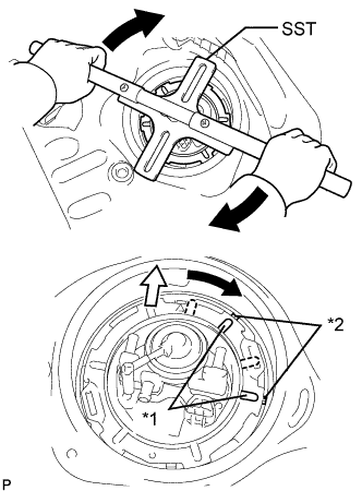
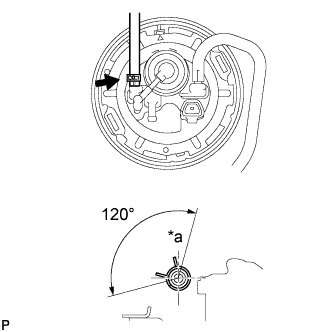
Text in Illustration *1 Protrusion *2 Groove 
Front of Vehicle Using SST, rotate the fuel pump gauge retainer so that the protrusions of the retainer are aligned with the grooves in the fuel tank assembly to install the fuel tank vent tube assembly to the fuel tank assembly.
-
Install the No. 1 fuel tube clamp.
-
Connect the charcoal canister outlet hose.
-
Text in Illustration *a Top Connect the No. 1 fuel evaporation tube sub-assembly with the clamp.
-
Connect the fuel tank EVAP/VENT tube.
-
-
INSTALL REAR FLOOR SERVICE HOLE COVER
-
Connect the fuel sender gauge connector.
-
Install the rear floor service hole cover with new butyl tape.
-
-
INSTALL FUEL SENDER GAUGE ASSEMBLY
-
Slide the fuel sender gauge assembly downwards and attach the claw labeled A to install the fuel sender gauge assembly.
-
Connect the fuel sender gauge connector.
Note
Do not touch the resistance plate or contacts of the fuel sender gauge assembly.
-
-
INSTALL FUEL SUCTION TUBE ASSEMBLY WITH PUMP AND GAUGE