FUEL PUMP INSTALLATION

-
INSTALL FUEL SUCTION TUBE ASSEMBLY WITH PUMP AND GAUGE
-
Install a new fuel suction tube set gasket to the fuel tank assembly.
-
Connect the fuel return vent tube sub-assembly and set the fuel suction tube assembly with pump and gauge into the fuel tank assembly.
Note
-
Be careful not to bend the arm of the fuel sender gauge.
-
When connecting the fuel tube connector, do not forcibly pull the fuel return vent tube sub-assembly.
-
-
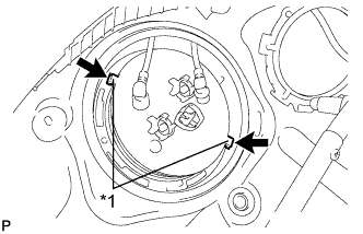
Text in Illustration *1 Protrusion 
Hole Align the protrusions of the fuel suction tube assembly with pump and gauge with the holes in the fuel tank assembly.
-
While pressing down on the fuel suction tube assembly with pump and gauge, temporarily install a new fuel pump gauge retainer.
-
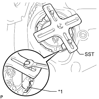
Text in Illustration *1 Insertion Point Set the 2 claws and plate of SST on the fuel pump gauge retainer.
- SST
- 09808-14030 ( 09808-01010, 09808-01030, 09808-01040 )
Tech Tips
Securely insert the ends of SST into the insertion points in the fuel pump gauge retainer.
-
While firmly pressing the claws of SST into the insertion points in the fuel pump gauge retainer, tighten the bolts of the claws.
-
Attach the handle of SST.
-
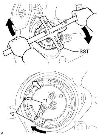
Text in Illustration *1 Protrusion *2 Groove 
Front of Vehicle Using SST, rotate the fuel pump gauge retainer so that the protrusions of the retainer are aligned with the grooves in the fuel tank assembly to install the fuel suction tube assembly with pump and gauge to the fuel tank assembly.
Note
-
Do not use any tools other than SST, such as a screwdriver, etc.
-
Do not use excessive force when pressing down on SST, as the fuel pump gauge retainer will place excessive force on the fuel suction tube assembly with pump and gauge and be difficult to remove, and parts may be damaged.
-
Be sure to keep the handle level when turning it, as SST may slip off the retainer if the handle is turned at an angle with excessive force.
-
Do not use an impact wrench or turn the handle with excessive force, as parts may be damaged.
-
If SST slips off the retainer, loosen the bolts and reattach SST to the retainer.
-
Make sure that the fuel suction tube set gasket does not come off.
-
-
Install the No. 1 fuel tube clamp.
-
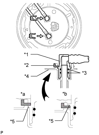
Text in Illustration *1 Fuel Tube Joint *2 Tube Joint Clip *3 O-Ring *4 Fuel Suction Plate Sub-assembly *5 Collar *a CORRECT *b INCORRECT Insert the fuel tank main tube sub-assembly and fuel tank return tube into the plugs of the fuel suction plate sub-assembly and fix them in place with the 2 tube joint clips.
Note
-
Check that there are no scratches or foreign objects on the connecting parts.
-
Check that the fuel tube joint is inserted securely.
-
Check that the tube joint clips are on the collars of the fuel tube joints.
-
After installing the tube joint clips, check that the fuel tube joints have not been pulled off.
-
Be careful not to damage any clips. If a clip is damaged, replace it.
-
-
Connect the fuel suction tube connector.
-
-
CONNECT CABLE TO NEGATIVE BATTERY TERMINAL
Note
When disconnecting the cable, some systems need to be initialized after the cable is reconnected Click here.
-
INSPECT FOR FUEL LEAK
-
Connect the GTS to the DLC3.
-
Turn the engine switch on (IG).
Note
Do not start the engine.
-
Turn the GTS on.
-
Enter the following menus: Powertrain / Engine and ECT / Active Test / Control the Fuel Pump / Speed.
-
-
Check the fuel pump operation.
-
Check for pressure in the fuel inlet tube from the fuel line. Check that sound of fuel flowing in the fuel tank can be heard.
If no sound can be heard, check the No. 1 integration relay, fuel pump, ECM and wiring connector.
-
-
Inspect for fuel leaks.
-
Check that there are no fuel leaks anywhere on the system after performing maintenance.
If there is a fuel leak, repair or replace parts as necessary.
-
-
-
INSTALL REAR FLOOR SERVICE HOLE COVER
-
Install the rear floor service hole cover with new butyl tape.
-
-
REMOVE NO. 3 ROOM PARTITION PAD
-
Install the No. 3 room partition pad with the clip.
-
-
INSTALL BENCH TYPE REAR SEAT CUSHION ASSEMBLY