FUEL TANK (w/o Canister Pump Module) INSTALLATION

-
INSTALL NO. 1 FUEL TANK PROTECTOR SUB-ASSEMBLY
-
Install the No. 2 fuel tank protector and No. 3 fuel tank protector to the fuel tank assembly.
-
Install the No. 1 fuel tank protector sub-assembly to the fuel tank assembly.
Tech Tips
Install the No. 1 fuel tank protector after installing the No. 2 fuel tank protector and No. 3 fuel tank protector.
-
-
INSTALL FUEL TANK CUSHION
-
Install 5 new No. 6 fuel tank cushions to the fuel tank assembly.
-
Install the fuel tank bracket, 2 fuel tank cushions and fuel tank cushion set to the fuel tank assembly.
-
-
INSTALL FUEL TUBE
-
Install the No. 5 fuel tube clamp to the fuel tank assembly.
-
Install the fuel tank return tube and fuel tank main tube sub-assembly to the fuel tank assembly with the clamp.
-
-
INSTALL CHARCOAL CANISTER OUTLET HOSE
-
Install the charcoal canister outlet hose and No. 4 fuel tube clamp to the fuel tank assembly.
-
-
INSTALL NO. 1 FUEL EVAPORATION TUBE SUB-ASSEMBLY
-
Install the No. 1 fuel tank evaporation tube sub-assembly to the fuel tank assembly.
-
-
INSTALL FUEL TANK ASSEMBLY
-
Set the fuel tank assembly on an engine lifter with attachments.
-
Using an engine lifter, slowly raise the fuel tank assembly, and then install the fuel tank assembly with the 2 nuts, 4 bolts and 2 No. 1 fuel tank band sub-assemblies.
- Torque:
- for nut
- 20 N*m { 200 kgf*cm, 14 ft.*lbf }
- for bolt
- 45 N*m { 459 kgf*cm, 33 ft.*lbf }
Note
Slowly raise the fuel tank assembly while being careful not to drop it.
-
-
INSTALL REAR SUSPENSION MEMBER BRACE
-
CONNECT CHARCOAL CANISTER OUTLET HOSE
-
Connect the charcoal canister outlet hose to the fuel tank filler pipe sub-assembly.
-
-
CONNECT FUEL TANK BREATHER TUBE
-
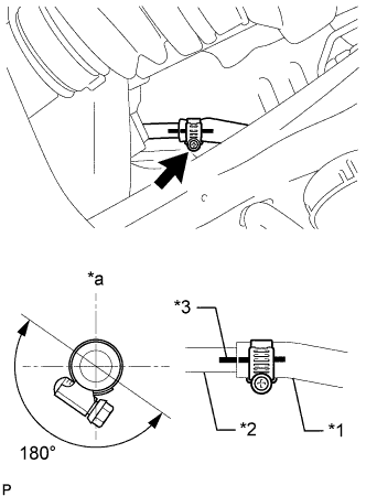
Text in Illustration *1 Fuel Tank Breather Tube *2 Fuel Tank Filler Pipe Sub-assembly *3 Alignment Mark *a Top Connect the fuel tank breather tube to the fuel tank filler pipe sub-assembly with the hose clamp.
Tech Tips
Make sure the fuel tank breather tube and hose clamp are oriented as shown in the illustration.
-
Connect the fuel tank breather tube to the 2 hose clamps.
-
-
CONNECT FUEL TANK TO FILLER PIPE HOSE
-
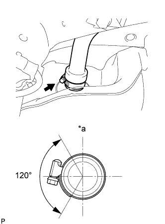
Text in Illustration *a Top Connect the fuel tank to filler pipe hose with the hose clamp.
Tech Tips
Make sure the hose clamp is oriented as shown in the illustration.
-
-
CONNECT FUEL TUBE
-

Text in Illustration *1 Retainer *2 Fuel Tube Connector *3 O-Ring *4 Pipe Align the axis of the fuel tube connector with the axis of the pipe, and then push on the fuel tube connector and press the retainer to connect the No. 1 fuel evaporation tube sub-assembly.
Note
-
Check for damage or foreign objects on the connected part.
-
After connecting, check that the fuel tube connector and the pipe are securely connected by pulling on them.
-
-
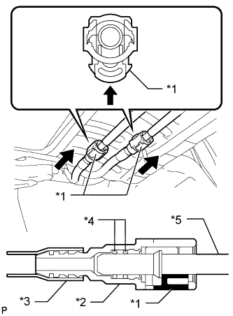
Text in Illustration *1 Retainer *2 Fuel Tube Connector *3 Nylon Tube *4 O-Ring *5 Pipe Align the axis of the fuel tube connector with the axis of the pipe, insert the fuel tube connector and push in the retainer to connect the fuel tank return tube and fuel tank main tube sub-assembly for the RH side.
Note
-
Check for damage or foreign objects on the connected part.
-
After connecting, check that the fuel tube connector and the pipe are securely connected by pulling on them.
-
-
-
INSTALL PROPELLER SHAFT WITH CENTER BEARING ASSEMBLY
-
ADD FUEL
-
INSTALL FUEL TANK VENT TUBE ASSEMBLY
-
INSTALL FUEL SUCTION TUBE ASSEMBLY WITH PUMP AND GAUGE