CAMSHAFT INSTALLATION

-
INSTALL CAMSHAFT TIMING GEAR ASSEMBLY
-
Clamp the camshaft in a vise.
Note
Be careful not to damage the camshaft in the vise.
-
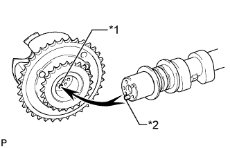
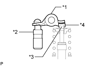
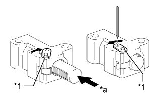
Text in Illustration *1 Pin Hole *2 Straight Pin Put the camshaft timing gear assembly and camshaft together by aligning the pin hole and straight pin.
-
Lightly press and turn the camshaft timing gear assembly against the camshaft, and press harder after the pin enters the hole.
Note
Be sure not to turn the camshaft timing gear assembly in the retard direction.
-
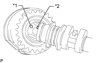
Check that there is no clearance between the camshaft timing gear assembly flange and camshaft.
-
Install the flange bolt while holding the camshaft.
- Torque:
- 100 N*m { 1020 kgf*cm, 74 ft.*lbf }
-
Check the lock of the camshaft timing gear assembly.
-
Secure the camshaft in place and confirm that the camshaft timing gear assembly is locked.
Note
Be careful not to damage the camshaft.
-
-
-
INSTALL CAMSHAFT TIMING EXHAUST GEAR ASSEMBLY
-
Clamp the camshaft in a vise.
Note
Be careful not to damage the camshaft in the vise.
-
Text in Illustration *1 Pin Hole *2 Straight Pin Put the camshaft timing exhaust gear assembly and camshaft together by aligning the pin hole and straight pin.
-
Lightly press and turn the camshaft timing gear assembly against the camshaft, and press harder after the pin enters the hole.
Note
Be sure not to turn the camshaft timing exhaust gear in the advanced direction.
-
Check that there is no clearance between the gear flange and camshaft.
-
Install the flange bolt while holding the camshaft.
- Torque:
- 100 N*m { 1020 kgf*cm, 74 ft.*lbf }
-
Check the camshaft timing exhaust gear lock.
-
Make sure that the camshaft timing exhaust gear assembly locks.
-
-
-
INSTALL NO. 3 CAMSHAFT SUB-ASSEMBLY
-
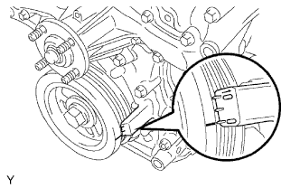
Check that the notch is aligned with the "0" timing mark of the timing chain cover.
-
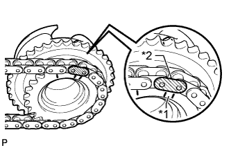
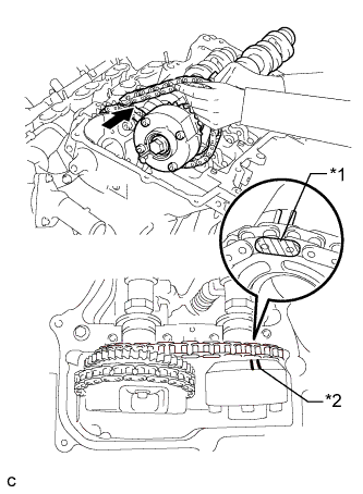
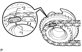
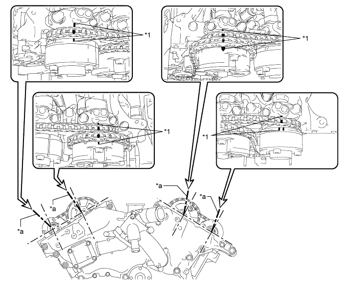
Text in Illustration *1 Timing Mark *2 Mark Plate (yellow) Align the mark plate (yellow) with the timing mark of the camshaft timing gear as shown in the illustration and install the No. 2 chain to the camshaft timing gear.
-
Clean the camshaft housing LH and camshaft journals, and apply engine oil to them.
-
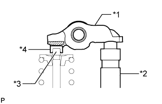
Text in Illustration *1 Valve Rocker Arm *2 Lash Adjuster *3 Valve Stem *4 Valve Stem Cap Make sure that the No. 1 valve rocker arm sub-assembly is installed as shown in the illustration.
-
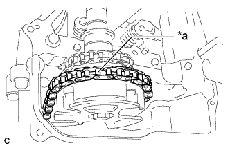
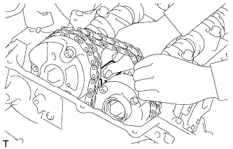
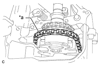
Text in Illustration *a Place on camshaft timing gear Install the chain to the No. 3 camshaft, and then install the camshaft to the camshaft housing LH.
Tech Tips
-
Place the chain on the camshaft timing gear but do not engage the teeth of the sprocket and the chain.
-
Install the camshaft so that the timing mark is facing upward.
-
-
-
INSTALL NO. 4 CAMSHAFT SUB-ASSEMBLY
-
Clean the camshaft housing LH and camshaft journals, and apply engine oil to them.
-
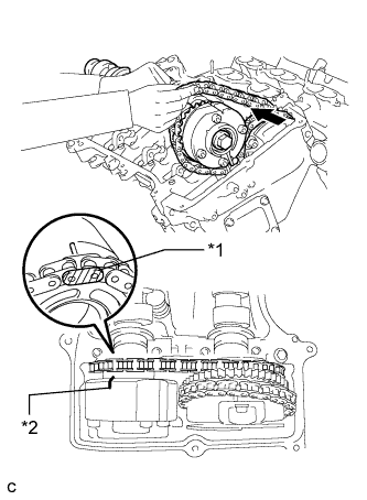
Text in Illustration *1 Mark Plate (yellow) *2 Timing Mark Pass the No. 4 camshaft through the No. 2 chain from the front of the vehicle, align the mark plate (yellow) with the timing mark and install the No. 2 chain to the camshaft timing exhaust gear.
-
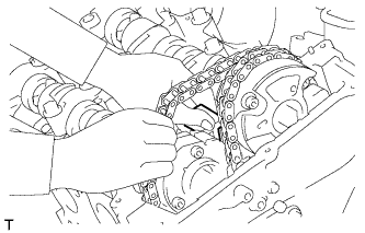
While lifting up the No. 4 camshaft, pass the No. 3 chain tensioner assembly through the No. 2 chain and set it in place.
-
Install the No. 4 camshaft to the camshaft housing LH, and then install the No. 3 chain tensioner assembly with the bolt.
- Torque:
- 21 N*m { 214 kgf*cm, 15 ft.*lbf }
-
-
INSTALL CAMSHAFT BEARING CAP (for Bank 2)
-
Clean the camshaft bearing caps and apply engine oil to them.
-
Text in Illustration *1 Valve Rocker Arm *2 Lash Adjuster *3 Valve Stem *4 Valve Stem Cap Make sure that the No. 1 valve rocker arm sub-assembly is installed as shown in the illustration.
-
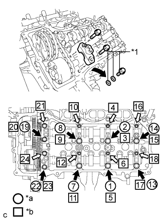
Text in Illustration *1 Service Bolts and Washers (used to temporarily secure the camshaft housing) *a Remove the service bolts and washers used to temporarily secure the camshaft housing *b Part to be Installed 
Bolt A 
Bolt B Check the marks and numbers on the camshaft bearing caps, and then remove the service bolts and washers in the order shown in the illustration. Immediately after removing the service bolts and washers in the locations for the bearing caps, install the bearing caps with the bolts in the order shown in the illustration.
- Torque:
- for Bolt A
- 28 N*m { 286 kgf*cm, 21 ft.*lbf }
- for Bolt B
- 16 N*m { 163 kgf*cm, 12 ft.*lbf }
Note
-
Be sure to follow the numerical order when performing this procedure.
-
Do not drop the service bolts and washers into the cylinder head.
-
Check the torque of each bolt again.
-
-
INSTALL CHAIN SUB-ASSEMBLY
-
Text in Illustration *1 Paint Mark Align the paint marks on the camshaft timing gear and No. 1 chain, and install the No. 1 chain to the camshaft timing gear.
Tech Tips
If the paint marks are not aligned, align them by turning the camshaft slightly.
-
-
INSTALL CAMSHAFT
-
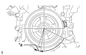
Text in Illustration *a 5 to 10° Turn the crankshaft clockwise until it is in the position shown in the illustration so that the chain can be installed easily.
Tech Tips
When turning the crankshaft, engine oil may spray out of the oil holes.
-
Text in Illustration *1 Timing Mark *2 Mark Plate (yellow) Align the mark plate (yellow) with the timing mark of the camshaft timing gear as shown in the illustration and install the No. 2 chain to the camshaft timing gear.
-
Clean the camshaft housing RH and camshaft journals and apply engine oil to them.
-
Text in Illustration *1 Valve Rocker Arm *2 Lash Adjuster *3 Valve Stem *4 Valve Stem Cap Make sure that the No. 1 valve rocker arm sub-assembly is installed as shown in the illustration.
-
Text in Illustration *a Place on camshaft timing gear Install the chain to the camshaft, and then install the camshaft to the camshaft housing RH.
Tech Tips
-
Place the chain on the camshaft timing gear but do not engage the teeth of the sprocket and the chain.
-
Install the camshaft so that the timing mark is facing upward.
-
-
-
INSTALL NO. 2 CAMSHAFT
-
Clean the camshaft housing RH and camshaft journals, and apply engine oil to them.
-
Text in Illustration *1 Mark Plate (yellow) *2 Timing Mark Pass the No. 2 camshaft through the No. 2 chain from the front of the vehicle, align the mark plate (yellow) with the timing mark and install the No. 2 chain to the camshaft timing exhaust gear.
-
While lifting up the No. 2 camshaft, pass the No. 2 chain tensioner assembly through the No. 2 chain and set it in place.
-
Install the No. 2 camshaft to the camshaft housing RH, and then install the No. 2 chain tensioner assembly with the bolt.
- Torque:
- 21 N*m { 214 kgf*cm, 15 ft.*lbf }
-
-
INSTALL CAMSHAFT BEARING CAP (for Bank 1)
-
Clean the camshaft bearing caps and apply engine oil to them.
-
Text in Illustration *1 Valve Rocker Arm *2 Lash Adjuster *3 Valve Stem *4 Valve Stem Cap Make sure that the No. 1 valve rocker arm sub-assembly is installed as shown in the illustration.
-
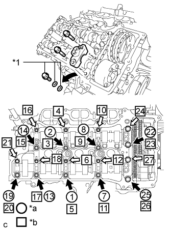
Text in Illustration *1 Service Bolt and Washers (used to temporarily secure the camshaft housing) *a Remove the service bolts and washers to temporarily secure the camshaft housing *b Part to be Installed Bolt A Bolt B Check the marks and numbers on the camshaft bearing caps, and then remove the service bolts and washers in the order shown in the illustration. Immediately after removing the service bolts and washers in the locations for the bearing caps, install the bearing caps with the bolts in the order shown in the illustration.
- Torque:
- for Bolt A
- 28 N*m { 286 kgf*cm, 21 ft.*lbf }
- for Bolt B
- 16 N*m { 163 kgf*cm, 12 ft.*lbf }
Note
-
Be sure to follow the numerical order when performing this procedure.
-
Do not drop the service bolts and washers into the cylinder head.
-
Check the torque of each bolt again.
-
-
INSTALL CHAIN SUB-ASSEMBLY
-
Text in Illustration *1 Paint Mark Align the paint marks on the camshaft timing gear and chain, and install the chain to the camshaft timing gear.
Tech Tips
If the paint marks are not aligned, align them by turning the camshaft slightly.
-
-
INSTALL NO. 1 CHAIN TENSIONER ASSEMBLY
-
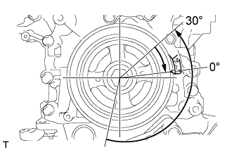
Turn the crankshaft counterclockwise 30° past the "0" timing mark, and then turn it clockwise to align the notch with the "0" timing mark.
-
Turn the crankshaft slightly to eliminate the slack in the chain.
Tech Tips
Make sure there is some slack in the chain around the area where the chain tensioner is installed.
-
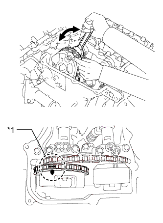
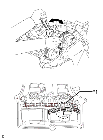
Text in Illustration *1 Stopper Plate *a Push While turning the stopper plate of the tensioner clockwise, push in the plunger of the tensioner as shown in the illustration.
-
While turning the stopper plate of the tensioner counterclockwise, insert a pin of 1.27 mm (0.0500 in.) diameter into the holes in the stopper plate and tensioner to secure the stopper plate in place.
-
Install the chain tensioner with the 2 bolts.
- Torque:
- 10 N*m { 102 kgf*cm, 7 ft.*lbf }
-
Remove the pin from the No. 1 chain tensioner.
-
-
INSPECT VALVE TIMING
-
Check the camshaft timing marks.
Note
-
Check each timing mark from a viewpoint directly in line with the center of the camshaft and the timing mark on each camshaft timing gear.
-
If the timing marks are checked from any other viewpoint, the valve timing may appear misaligned.
-
-
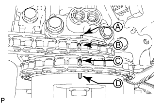
Check that each camshaft timing mark is positioned as shown in the illustration.
Text in Illustration *1 Timing Mark - - *a Viewpoint - - Tech Tips
For Intake Camshaft: Be sure to check mark A at the point when marks B, C and D are positioned in line. If the marks are checked from any other viewpoint, they cannot be checked correctly.
-
If the valve timing is misaligned, reinstall the timing chain.
-
Turn the crankshaft 2 revolutions, set the No. 1 cylinder to TDC/compression and check the timing marks again.
-
-
INSTALL TIMING CHAIN COVER PLATE
-
Install a new gasket and the timing chain cover plate with the 4 bolts.
- Torque:
- 9.1 N*m { 93 kgf*cm, 81 in.*lbf }
-
-
INSTALL SPARK PLUG TUBE GASKET
-
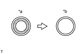
Text in Illustration *a Before cutting off *b After cutting off 
Area to be cut off Using a cutter, cut off the sealing part of the removed plug tube gasket.
-
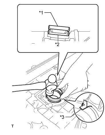
Text in Illustration *1 Plug tube gasket without sealing part *2 New plug tube gasket *3 Claw Using a plug tube gasket which has had the sealing part cut off, uniformly press in a new plug tube gasket all the way.
Note
-
Keep the lip free of foreign matter.
-
Do not tap on the oil seal at an angle.
Tech Tips
If a plug tube gasket that will be used to install a new gasket is deformed, and cannot be positioned on a new gasket, correct the deformation using pliers.
-
-
Return the claws of the ventilation baffle plate to their original positions.
-
-
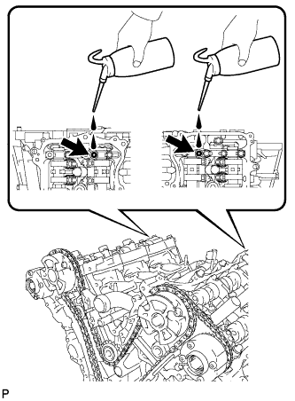
POUR ENGINE OIL
Tech Tips
Before installing the cylinder head cover, pour engine oil into the locations shown in the illustration.
-
INSTALL CYLINDER HEAD COVER SUB-ASSEMBLY
-
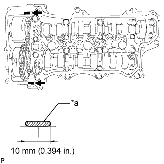
Text in Illustration *a 2.0 to 3.0 mm Seal Packing Apply seal packing as shown in the illustration.
Seal packing Toyota Genuine Seal Packing Black, Three Bond 1207B or equivalent Note
-
Remove any oil from the contact surface.
-
Install the head cover within 3 minutes after applying seal packing.
-
Do not start the engine for at least 2 hours after installation.
-
-
Install 3 new gaskets to the camshaft bearing caps.
-
Install a new gasket to the head cover.
-
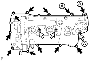
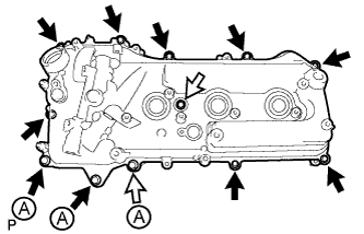
Apply adhesive to the threads of the 11 cylinder head cover bolts indicated by the black arrows in the illustration.
Adhesive Toyota Genuine Adhesive 1324, Three Bond 1324 or equivalent. Text in Illustration Apply adhesive to these bolts -
Install the head cover with the 14 bolts.
- Torque:
- for bolt A
- 21 N*m { 214 kgf*cm, 15 ft.*lbf }
- except bolt A
- 10 N*m { 102 kgf*cm, 7 ft.*lbf }
-
Attach the clamps and connect the connectors to connect the cylinder head cover.
-
-
INSTALL CYLINDER HEAD COVER SUB-ASSEMBLY LH
-
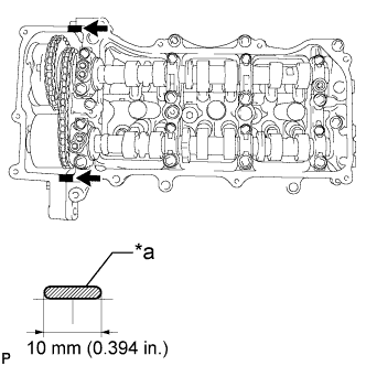
Text in Illustration *a 2.0 to 3.0 mm Seal Packing Apply seal packing as shown in the illustration.
Seal packing Toyota Genuine Seal Packing Black, Three Bond 1207B or equivalent Note
-
Remove any oil from the contact surface.
-
Install the head cover within 3 minutes after applying seal packing.
-
Do not start the engine for at least 2 hours after installation.
-
-
Install 3 new gaskets to the camshaft bearing caps.
-
Install a new gasket to the head cover.
-
Apply adhesive to the threads of the 11 cylinder head cover bolts indicated by the black arrows in the illustration.
Adhesive Toyota Genuine Adhesive 1324, Three Bond 1324 or equivalent. Text in Illustration Apply adhesive to these bolts -
Install the head cover with the 12 bolts.
- Torque:
- for bolt A
- 21 N*m { 214 kgf*cm, 15 ft.*lbf }
- except bolt A
- 10 N*m { 102 kgf*cm, 7 ft.*lbf }
-
Attach the clamps and connect the connectors to connect the cylinder head cover LH.
-
-
INSTALL NO. 2 OIL PIPE
-
Make sure that there is no foreign matter on the mesh of the oil control valve filter RH.
Note
Do not touch the mesh when installing the oil control valve filter.
-
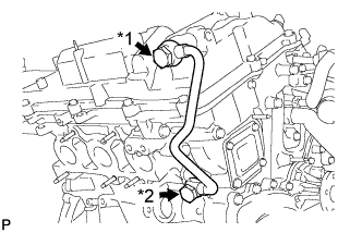
Text in Illustration *1 Oil Pipe Union *2 Oil Check Valve Bolt Install the oil control valve filter RH to the oil pipe union. Install new gaskets and temporarily install the oil pipe (on the head cover side).
-
Install a new gasket and temporarily install the oil pipe (on the cylinder head side) with the oil check valve bolt.
-
Tighten the oil pipe union (on the head cover side).
- Torque:
- 60 N*m { 612 kgf*cm, 44 ft.*lbf }
-
Tighten the oil check valve bolt (on the cylinder head side).
- Torque:
- 60 N*m { 612 kgf*cm, 44 ft.*lbf }
Note
If the link that connects the gaskets is broken, remove the connecting link by using nippers or similar tools.
-
-
INSTALL NO. 1 OIL PIPE
-
Make sure that there is no foreign matter on the mesh of the oil control valve filter LH.
Note
Do not touch the mesh when installing the oil control valve filter.
-
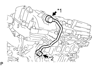
Text in Illustration *1 Oil Pipe Union *2 Oil Check Valve Bolt Install the oil control valve filter LH to the oil pipe union. Install new gaskets and temporarily install the oil pipe (on the head cover side).
-
Install a new gasket and temporarily install the oil pipe (on the cylinder head side) with the oil check valve bolt.
-
Tighten the oil pipe union (on the head cover side).
- Torque:
- 60 N*m { 612 kgf*cm, 44 ft.*lbf }
-
Tighten the oil check valve bolt (on the cylinder head side).
- Torque:
- 60 N*m { 612 kgf*cm, 44 ft.*lbf }
Note
If the link that connects the gaskets is broken, remove the connecting link by using nippers or similar tools.
-
-
INSTALL NO. 2 ENGINE OIL LEVEL DIPSTICK GUIDE
-
Install a new O-ring to the No. 2 oil level dipstick guide.
-
Install the No. 2 oil level dipstick guide with the bolt.
- Torque:
- 21 N*m { 214 kgf*cm, 15 ft.*lbf }
-
Install the oil level dipstick.
-
-
INSTALL SPARK PLUG
-
Install the 6 spark plugs.
- Torque:
- 18 N*m { 184 kgf*cm, 13 ft.*lbf }
-
-
INSTALL IGNITION COIL ASSEMBLY
-
Install the 6 ignition coils with the 6 bolts.
- Torque:
- 10 N*m { 102 kgf*cm, 7 ft.*lbf }
-
Connect the 6 ignition coil connectors.
-
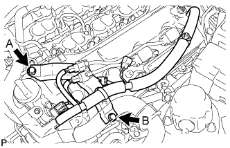
Connect the wire harness bracket with the 2 bolts.
- Torque:
- for bolt A
- 10 N*m { 102 kgf*cm, 7 ft.*lbf }
- for bolt B
- 21 N*m { 214 kgf*cm, 15 ft.*lbf }
-
Connect the wire harness with the 2 nuts.
- Torque:
- 10 N*m { 102 kgf*cm, 7 ft.*lbf }
-
-
INSTALL INJECTOR DRIVER
Note
-
Be careful not to drop or strike the injector driver.
-
The injector driver is grounded at the bolt and nut. To ensure that it is grounded, clean all oil and foreign matter from the installation areas of the injector driver and engine before installing the injector driver.
-
Install the injector driver with the bolt and 2 nuts.
- Torque:
- 10 N*m { 102 kgf*cm, 7 ft.*lbf }
-
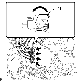
Text in Illustration *1 Lock Lever Connect the 4 connectors to the injector driver. Move the lock levers in the direction indicated by the arrow to lock the 3 connectors.
-
-
INSTALL NO. 1 ENGINE COVER
-
Install the No. 1 engine cover with the 3 clips.
-
-
INSTALL GENERATOR ASSEMBLY
-
INSTALL FUEL PUMP ASSEMBLY
-
INSTALL BATTERY