ENGINE UNIT REMOVAL

-
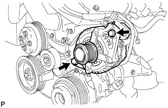
REMOVE FAN AND GENERATOR V BELT
-
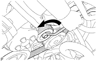
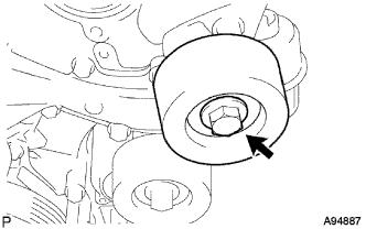
While releasing the belt tension by turning the belt tensioner counterclockwise, remove the V belt from the belt tensioner.
-
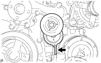
While turning the belt tensioner counterclockwise, align its holes, and then insert the 5 mm bi-hexagon wrench into the holes to secure the belt tensioner.
-
-
REMOVE NO. 2 ENGINE COVER
-
Remove the 3 clips and clamp, then remove the No. 2 engine cover.
-
-
REMOVE NO. 1 ENGINE COVER
-
Remove the 3 clips, then remove the No. 1 engine cover.
-
-
REMOVE NO. 2 IDLER PULLEY SUB-ASSEMBLY
-
Remove the bolt, No. 2 idler pulley cover plate and No. 2 idler pulley sub-assembly.
-
-
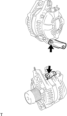
REMOVE GENERATOR ASSEMBLY
-
Remove the terminal cap.
-
Remove the nut and disconnect the generator wire.
-
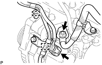
Disconnect the generator connector, and detach the 2 clamps.
-
Disconnect the connector from the cooling fan ECU.
-
Remove the nut, and disconnect the bracket.
-
Remove the 2 bolts and generator.
-
Remove the 2 bolts and 2 brackets.
-
-
REMOVE COOLER COMPRESSOR ASSEMBLY
-
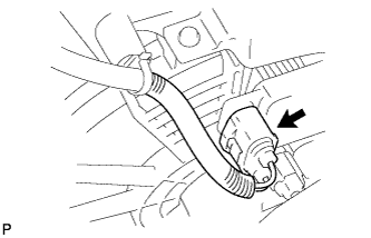
Disconnect the connector.
-
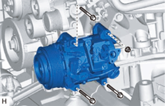
Remove the 3 bolts and nut.
-
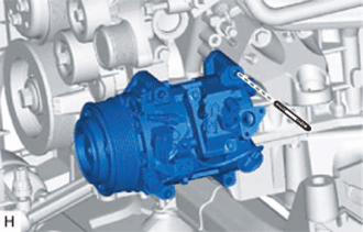
Using an E8 "torx" socket, remove the stud bolt and cooler compressor assembly.
-
-
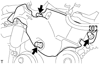
REMOVE FRONT NO. 1 ENGINE MOUNTING BRACKET LH
-
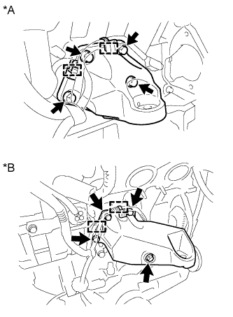
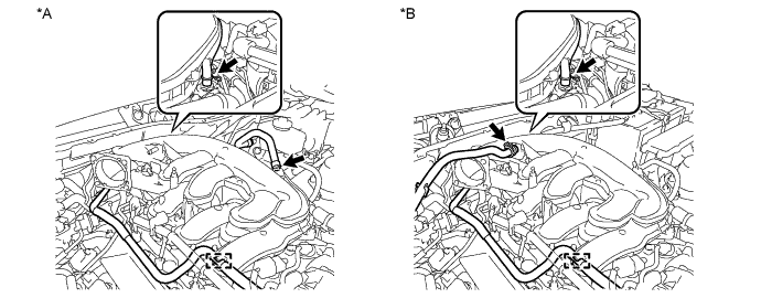
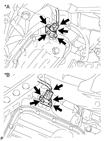
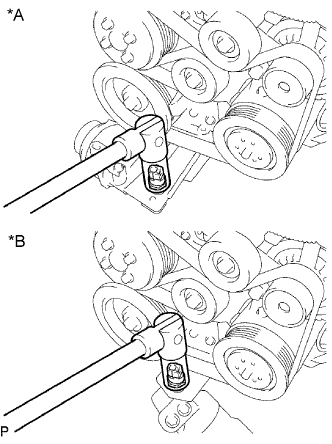
Text in Illustration *A for 2WD *B for AWD Disconnect the 2 clamps.
-
Remove the 4 bolts and front No. 1 engine mounting bracket LH.
-
-
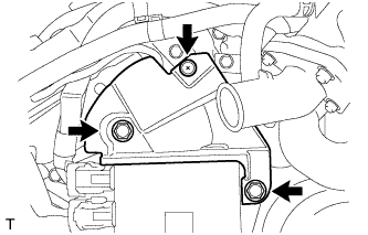
REMOVE FRONT NO. 1 ENGINE MOUNTING BRACKET RH
-
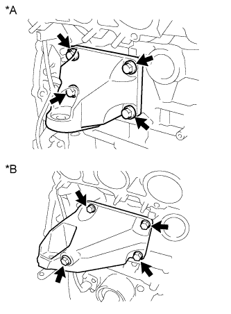
Text in Illustration *A for 2WD *B for AWD Remove the 4 bolts and front No. 1 engine mounting bracket RH.
-
-
REMOVE V-RIBBED BELT TENSIONER ASSEMBLY
-
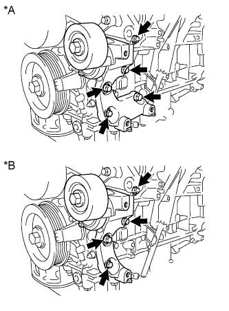
Text in Illustration *A for 2WD *B for AWD for 2WD:
Remove the 5 bolts, then remove the V-ribbed belt tensioner assembly.
-
for AWD:
Remove the 4 bolts, then remove the V-ribbed belt tensioner assembly.
-
-
REMOVE WATER PUMP PULLEY
-
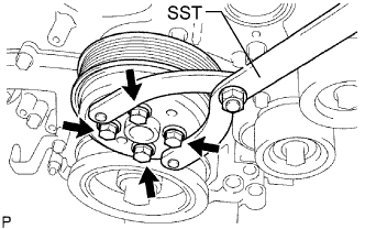
Using SST, hold the water pump pulley.
- SST
- 09960-10010 ( 09962-01000, 09963-00700 )
-
Remove the 4 bolts and water pump pulley.
-
-
REMOVE ENGINE WIRE
-
REMOVE INJECTOR DRIVER
-
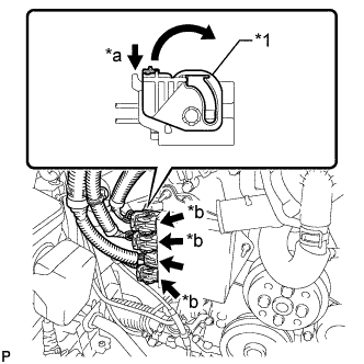
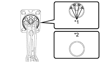
Text in Illustration *1 Lock Lever *a Release *b Lock with Connector Move the lock levers in the direction indicated by the arrow to release the 3 connector locks. Disconnect the 4 connectors from the injector driver.
-
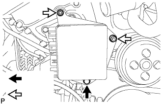
Remove the bolt, 2 nuts and injector driver.
Note
Be careful not to drop or strike the injector driver.
-
-
REMOVE THROTTLE WITH MOTOR BODY ASSEMBLY
-
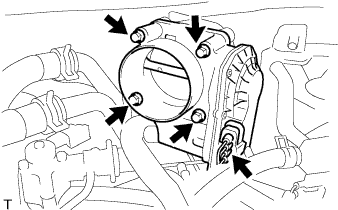
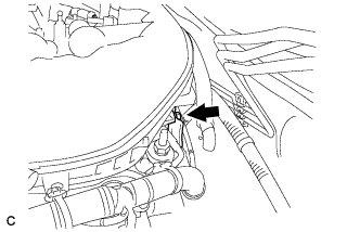
Disconnect the throttle motor connector.
-
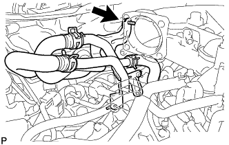
Remove the 4 bolts and disconnect the throttle body with motor assembly from the intake air surge tank.
-
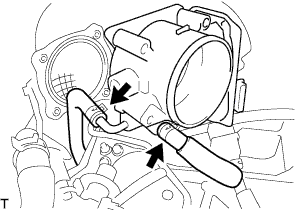
Disconnect the 2 water by-pass hoses from the throttle body with motor assembly.
-
Remove the throttle body with motor assembly and gasket.
-
-
REMOVE INTAKE AIR SURGE TANK ASSEMBLY
-
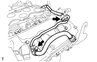
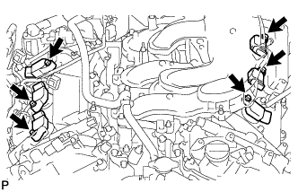
Disconnect the PCV hose, union to check valve hose and water by-pass hose.
Text in Illustration *A for LHD *B for RHD -
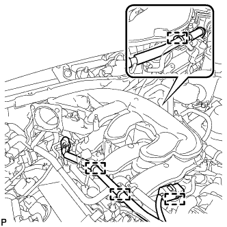
for LHD:
Disconnect the 4 wire harness clamps.
-
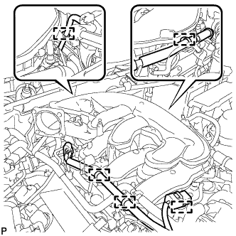
for RHD:
Disconnect the 5 wire harness clamps.
-
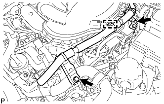
Remove the bolt and No. 3 water by-pass pipe.
-
Remove the bolt and separate the No. 2 surge tank stay from the intake air surge tank assembly.
-
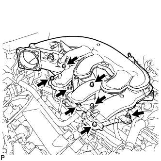
Remove the 2 nuts from the intake air surge tank assembly.
-
Using a 5 mm long hexagon socket wrench, remove the 6 bolts.
-
Remove the intake air surge tank assembly and gasket.
-
-
REMOVE NO. 2 SURGE TANK STAY
-
Remove the bolt and No. 2 surge tank stay.
-
-
REMOVE NO. 3 WATER BY-PASS PIPE
-
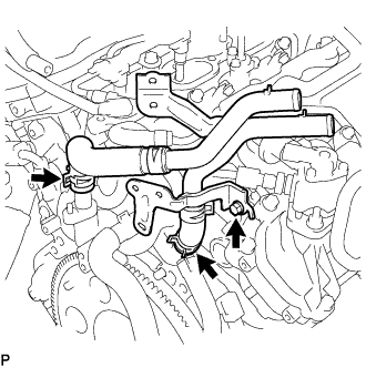
Remove the bolt, and disconnect the 2 hoses and No. 3 water by-pass pipe.
-
-
REMOVE INTAKE MANIFOLD
-
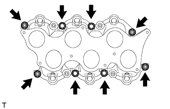
Remove the 4 bolts, 4 nuts, intake manifold and 2 gaskets.
-
-
REMOVE FUEL TUBE SUB-ASSEMBLY
-
Remove the 2 bolts and fuel tube sub-assembly.
-
-
REMOVE FUEL PRESSURE PULSATION DAMPER ASSEMBLY
-
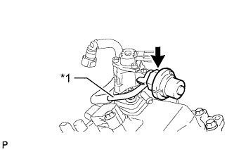
Text in Illustration *1 Fuel Tube Sub-assembly Remove the fuel pressure pulsation damper and 2 gaskets, and disconnect the fuel tube from the fuel pump.
-
-
REMOVE NO. 1 FUEL PIPE SUB-ASSEMBLY
-
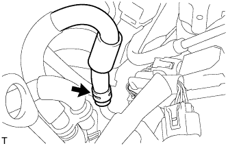
Disconnect the No. 2 fuel hose from the No. 1 fuel pipe sub-assembly.
-
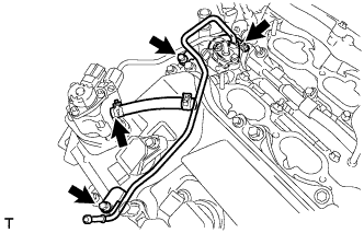
Disconnect the 2 fuel hoses.
-
Remove the 2 bolts and No. 1 fuel pipe sub-assembly.
-
-
DISCONNECT NO. 2 FUEL PIPE SUB-ASSEMBLY
-
Disconnect the fuel high pressure side fuel pump connector.
-
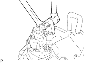
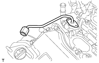
Secure the union bolt on the fuel pump side in place with a 21 mm wrench. Using a 19 mm union nut wrench, loosen the union and remove the fuel pipe.
Note
-
There must be absolutely no free play in the union on the fuel pump side.
-
If the union on the fuel pump side has free play, replace the fuel pump.
-
-
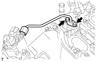
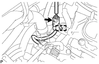
Remove the 2 bolts on the delivery pipe side.
Note
-
Do not remove the fuel pipe from the delivery pipe. Only remove the 2 bolts.
-
If the No. 2 fuel pipe is accidentally removed, replace its O-ring, No. 1 backup ring and No. 2 backup ring.
-
-
-
REMOVE FUEL PUMP ASSEMBLY
-
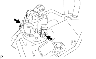
Remove the 2 nuts, fuel pump and fuel pump insulator.
-
-
REMOVE NO. 3 FUEL PIPE SUB-ASSEMBLY
-
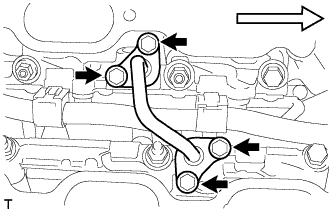
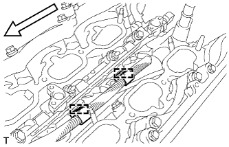
Remove the 4 bolts and fuel pipe from the fuel delivery pipe sub-assembly.
Text in Illustration 
Front Note
Pull and remove the fuel pipe in a straight line to avoid damage to the seal surface of the delivery pipe O-rings.
-
Remove the O-rings, backup rings and E-rings from the No. 3 fuel pipe sub-assembly.
-
-
REMOVE NO. 2 FUEL PIPE SUB-ASSEMBLY
-
Remove the No. 2 fuel pipe sub-assembly from the fuel delivery pipe.
Note
Pull and remove the No. 2 fuel pipe sub-assembly in a straight line to avoid damage to the seal surface of the delivery pipe O-ring.
-
Remove the O-ring, backup rings and E-ring from the No. 2 fuel pipe sub-assembly.
-
-
REMOVE FUEL DELIVERY PIPE SUB-ASSEMBLY
-
Disconnect the fuel pressure sensor connector.
-
Detach the wire harness clamp.
-
Disconnect the 2 wire harness clamps.
Text in Illustration Front -
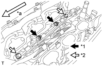
Text in Illustration *1 Nut *2 Bolt *a Front Remove the 2 bolts and 2 nuts.
-
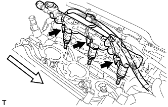
With the connectors still connected, disconnect the No. 1 fuel delivery pipe.
Text in Illustration Front Note
-
Be extremely careful not to touch or strike the tips of the injectors.
-
Pull and remove the fuel pipe in a straight line without tilting it.
-
-
Disconnect the 3 injector connectors.
-
Remove the 3 injector vibration insulators from the cylinder head.
-
-
REMOVE NO. 2 FUEL DELIVERY PIPE SUB-ASSEMBLY
-
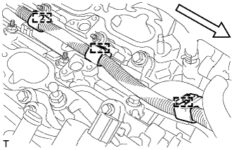
Disconnect the 3 wire harness clamps.
Text in Illustration Front -
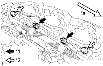
Text in Illustration *1 Nut *2 Bolt *a Front Remove the 2 bolts and 2 nuts.
-
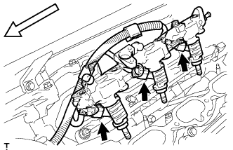
With the connectors still connected, disconnect the No. 2 fuel delivery pipe.
Text in Illustration Front Note
-
Make sure that the fuel delivery pipe is disconnected from the delivery pipe (LH side).
-
Be extremely careful not to touch or strike the tips of the injectors.
-
Pull and remove the fuel pipe in a straight line without tilting it.
-
-
Disconnect the 3 injector connectors.
-
Remove the 3 injector vibration insulators from the cylinder head.
-
-
REMOVE FUEL INJECTOR ASSEMBLY
-
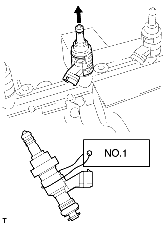
Secure the delivery pipe in a vise between aluminum plates and pull out the injector in a straight line.
Note
-
Pull and remove the injector in a straight line to avoid damage to the seal surface of the delivery pipe O-ring.
-
For reinstallation, attach a tag or label to the injector shaft.
-
-
Remove the nozzle holder clamps from the injectors.
-
Remove the O-ring, backup rings and E-ring from the fuel injector.
-
-
REMOVE FUEL INJECTOR SEAL
-
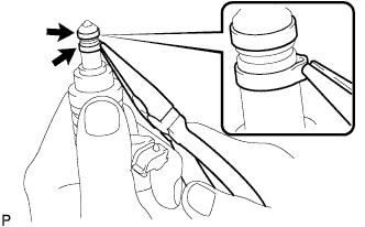
Using the tips of a pair of needle nose pliers, pinch and pull one of the 2 injector seals at several points to stretch it. Repeat this for the other injector seal.
Note
-
Excessively pinching the injector seal may damage the groove of the injector.
-
If an injector is dropped or the tips of the injectors are struck, replace it with a new one.
-
-
Remove the 2 injector seals from the injector.
-
-
REMOVE V-BANK COVER BRACKET SUB-ASSEMBLY
-
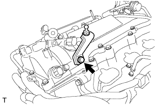
Remove the bolt and V-bank cover bracket.
-
-
REMOVE IGNITION COIL ASSEMBLY
-
Remove the 2 nuts and disconnect the wire harness.
-
Disconnect the wire harness clamp.
-
Remove the 2 bolts and disconnect the 2 wire harness brackets.
-
Disconnect the 6 ignition coil connectors.
-
Remove the 6 bolts and the 6 ignition coil assemblies.
-
-
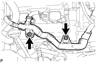
REMOVE ENGINE OIL LEVEL SENSOR
-
Text in Illustration *A for 2WD *B for AWD Disconnect the engine oil level sensor connector.
-
Remove the 4 bolts and engine oil level sensor.
-
Text in Illustration *1 Cutting Position *2 Supply Part Cut off the gasket as shown in the illustration.
-
Remove the gasket from the engine oil level sensor.
Tech Tips
After cutting away the parts of the gasket shown in the illustration, remove only the outer part of the gasket.
-
-
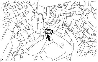
REMOVE ENGINE OIL PRESSURE SWITCH ASSEMBLY
-
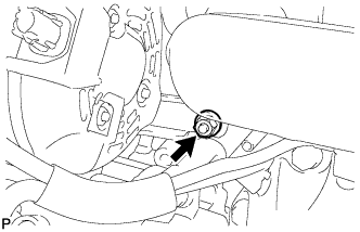
Disconnect the engine oil pressure switch connector.
-
Text in Illustration *A for 2WD *B for AWD Using a 24 mm deep socket wrench, remove the engine oil pressure switch.
-
-
REMOVE ENGINE COOLANT TEMPERATURE SENSOR
-
Disconnect the engine coolant temperature sensor connector.
-
Remove the engine coolant temperature sensor and gasket.
-