CYLINDER HEAD GASKET INSTALLATION

-
INSTALL CYLINDER HEAD GASKET
-
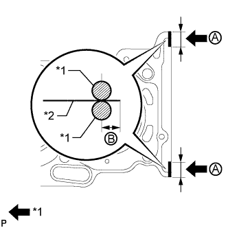
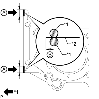
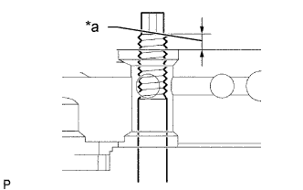
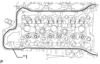
Text in Illustration *1 Seal Packing *2 Gasket Apply a continuous line of seal packing to a new cylinder head gasket as shown in the illustration.
Seal packing Toyota Genuine Seal Packing Black, Three Bond 1207B or equivalent Seal diameter 2.5 to 3.0 mm (0.0984 to 0.118 in.) Seal Packing Application Range A 10 to 15 mm (0.394 to 0.591 in.) B 1.25 to 1.50 mm (0.0492 to 0.0591 in.) Note
-
Remove any oil from the contact surface.
-
Install the cylinder head gasket within 3 minutes after applying the seal packing.
-
Do not apply engine oil within 2 hours of installation.
-
-
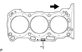
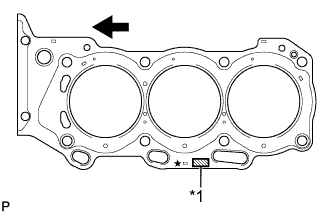
Text in Illustration *1 Lot No. 
Engine Front Place the cylinder head gasket on the cylinder block surface with the Lot No. stamp upward.
Note
-
Be careful of the installation direction.
-
Gently place the cylinder head in order not to damage the gasket with the bottom part of the head.
-
-
-
INSTALL CYLINDER HEAD SUB-ASSEMBLY
-
Place the cylinder head on the cylinder block.
Note
Be careful not to allow oil to adhere to the bottom part of the cylinder head.
Tech Tips
The cylinder head bolts are tightened in 3 progressive steps.
-
Apply a light coat of engine oil to the threads and under the heads of the cylinder head bolts.
-
Step 1:
-
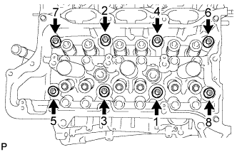
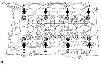
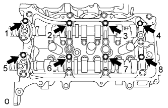
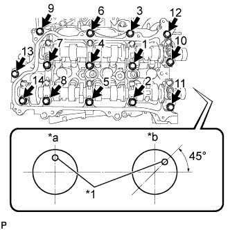
Using a 10 mm bi-hexagon wrench, install and uniformly tighten the 8 cylinder head bolts with the plate washers in several steps and in the sequence shown in the illustration.
- Torque:
- 36 N*m { 367 kgf*cm, 27 ft.*lbf }
-
-
Step 2:
-
Mark the front side of each cylinder head bolt head with paint.
-
Tighten the cylinder head bolts another 90°.
-
-
Step 3:
-
Tighten the cylinder head bolts an additional 90°.
-
Check that the paint marks are now at a 180° angle to the front.
-
-
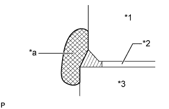
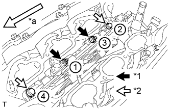
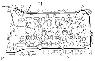
Text in Illustration *1 Cylinder Head *2 Cylinder Head Gasket *3 Cylinder Block *a Wipe Clean Thoroughly wipe off seal packing that has seeped out onto the front side of the engine.
-
-
INSTALL NO. 2 CYLINDER HEAD GASKET
-
Text in Illustration *1 Seal Packing *2 Gasket Apply a continuous line of seal packing to a new No. 2 cylinder head gasket as shown in the illustration.
Seal packing Toyota Genuine Seal Packing Black, Three Bond 1207B or equivalent Seal diameter 2.5 to 3.0 mm (0.0984 to 0.118 in.) Seal Packing Application Range A 10 to 15 mm (0.394 to 0.591 in.) B 1.25 to 1.50 mm (0.0492 to 0.0591 in.) Note
-
Remove any oil from the contact surface.
-
Install the cylinder head gasket within 3 minutes after applying the seal packing.
-
Do not start the engine for at least 2 hours after installation.
-
-
Text in Illustration *1 Lot No. Engine Front Place the cylinder head gasket on the cylinder block surface with the Lot No. stamp upward.
Note
-
Be careful of the installation direction.
-
Gently place the cylinder head in order not to damage the gasket with the bottom part of the head.
-
-
-
INSTALL CYLINDER HEAD LH
-
Place the cylinder head on the cylinder block.
Note
Be careful not to allow oil to adhere to the bottom part of the cylinder head.
Tech Tips
The cylinder head bolts are tightened in 3 progressive steps.
-
Apply a light coat of engine oil to the threads and under the heads of the cylinder head bolts.
-
Step 1:
-
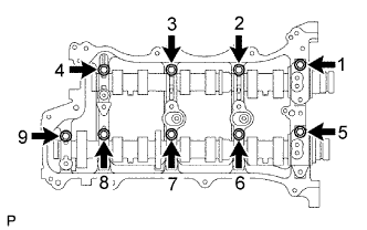
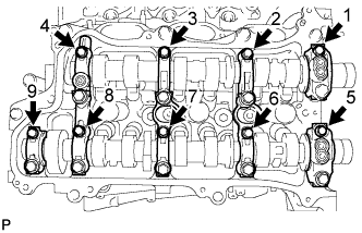
Using a 10 mm bi-hexagon wrench, install and uniformly tighten the 8 cylinder head bolts with the plate washers in several steps in the sequence shown in the illustration.
- Torque:
- 36 N*m { 367 kgf*cm, 27 ft.*lbf }
-
-
Step 2:
-
Mark the front side of each cylinder head bolt head with paint.
-
Tighten the cylinder head bolts another 90°.
-
-
Step 3:
-
Tighten the cylinder head bolts an additional 90°.
-
Check that the paint marks are now at a 180° angle to the front.
-
-
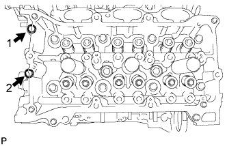
Tighten the 2 bolts in the order shown in the illustration.
- Torque:
- 30 N*m { 306 kgf*cm, 22 ft.*lbf }
-
Text in Illustration *1 Cylinder Head *2 Cylinder Head Gasket *3 Cylinder Block *a Wipe Clean Thoroughly wipe off seal packing that has seeped out onto the front side of the engine.
-
-
INSTALL FUEL INJECTOR SEAL
-
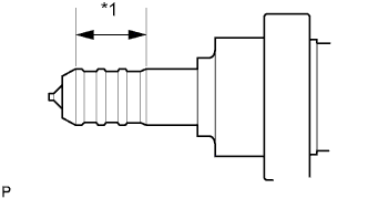
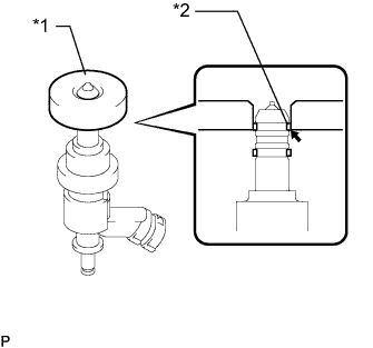
Text in Illustration *1 Clean Area Apply engine conditioner to the injector area shown in the illustration. Using a piece of cloth, clean carbon deposits from the injector and its grooves.
Note
-
Do not clean the tip of the injector.
-
Do not use a wire brush to clean the injector.
-
If an injector is dropped or the tips of the injectors are struck, replace it with a new one.
-
-
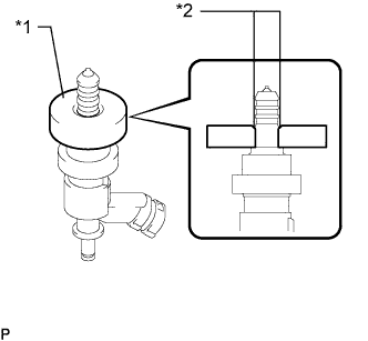
Text in Illustration *1 SST (Guide) *2 Tapered Inner Portion Apply engine oil to the injector contact surface of SST (guide). Then attach SST (guide) to the injector with the tapered inner portion facing the tip of the injector, as shown in the illustration.
- SST
- 09260-39015 ( 09268-03020 )
-
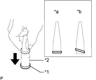
Text in Illustration *1 Fuel Injector Seal *2 SST (Holder) *a CORRECT *b INCORRECT Install a new injector seal to SST (holder).
- SST
- 09260-39015 ( 09268-03010 )
Note
Be careful not to install the injector seal to SST (holder) at an angle. Doing so will stretch the seal and correcting this problem is very complicated.
-
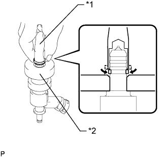
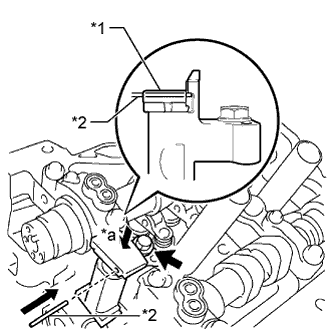
Text in Illustration *1 SST (Holder) *2 SST (Guide) Install SST (holder with injector seal) to the tip of the injector. Slide the seal downward into the injector groove (injector connector side) with your fingers, as shown in the illustration.
- SST
- 09260-39015 ( 09268-03010, 09268-03020 )
Tech Tips
Check that the seal covers the circumference of the injector groove as shown in the illustration.
-
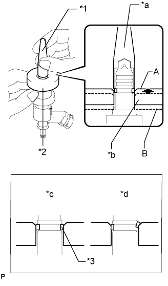
Text in Illustration *1 SST (Holder) *2 SST (Guide) *3 Injector Seal *a Gently Press *b Slowly Slide *c CORRECT *d INCORRECT Using SST (holder), gently press downward on the injector seal (injector connector side). Then slowly slide SST (guide) toward the injector tip to settle the seal into the injector groove.
- SST
- 09260-39015 ( 09268-03010, 09268-03020 )
Note
Be careful that the seal is not pinched between SST (guide) and the injector groove. Replace the seal if it becomes damaged.
Tech Tips
-
When using SST (guide) to settle the seal into the groove, SST (guide) only needs to be slid upward to the position labeled A in the illustration.
-
After using SST (guide) to settle the seal into the groove, return SST (guide) to its position labeled B in the illustration.
-
Text in Illustration *1 Fuel Injector Seal *2 SST (Holder) *a CORRECT *b INCORRECT Install a new injector seal to the injector groove (injector tip side) as shown in the illustration.
- SST
- 09260-39015 ( 09268-03010 )
-
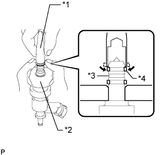
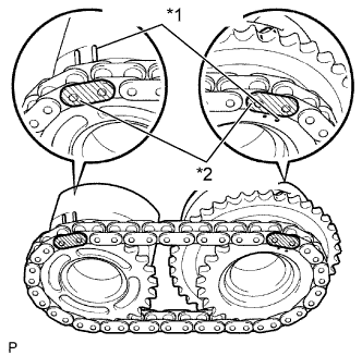
Text in Illustration *1 SST (Holder) *2 SST (Guide) *3 Welded Groove *4 Injector Seal Check that the seal covers the circumference of the injector groove as shown in the illustration.
- SST
- 09260-39015 ( 09268-03010, 09268-03020 )
Note
Make sure that the seal does not slip into the welded groove of the injector shown in the illustration. If it does, replace it with a new one.
-
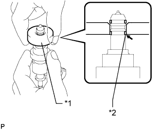
Text in Illustration *1 SST (Guide) *2 Injector Seal Slowly slide SST (guide) toward the tip of the injector. When the injector contact surface of SST (guide) aligns with the seal (injector connector side) as shown in the illustration, hold the position for 5 seconds or more to fully align the seal into the injector groove.
- SST
- 09260-39015 ( 09268-03020 )
Note
Be careful that the seal is not pinched between SST (guide) and the injector groove. Replace the seal if it becomes damaged.
Tech Tips
-
Set SST (guide) so that its bottom surface and seal are flush.
-
If there is difficulty in sliding SST upward, slowly wiggle it from side to side while sliding it up the injector little by little.
-
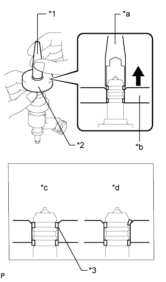
Text in Illustration *1 SST (Holder) *2 SST (Guide) *3 Injector Seal *a Gently Press *b Slide *c CORRECT *d INCORRECT Using SST (holder), gently press downward on the injector seal (injector tip side). Then slowly slide SST (guide) toward the injector tip to settle the seal into the injector groove.
- SST
- 09260-39015 ( 09268-03010, 09268-03020 )
Note
Be careful that the seal is not pinched between SST (guide) and the injector groove. Replace the seal if it becomes damaged.
-
Text in Illustration *1 SST (Guide) *2 Injector Seal Slowly slide SST (guide) toward the tip of the injector. When the injector contact surface of SST (guide) aligns with the seal (injector tip side) as shown in the illustration, hold the position for 5 seconds or more to fully align the seal into the injector groove.
- SST
- 09260-39015 ( 09268-03020 )
Note
Be careful that the seal is not pinched between SST (guide) and the injector groove. Replace the seal if it becomes damaged.
Tech Tips
-
Set SST (guide) so that its bottom surface and the seal are flush.
-
If there is difficulty in sliding SST upward, slowly wiggle it from side to side while sliding it up the injector little by little.
-
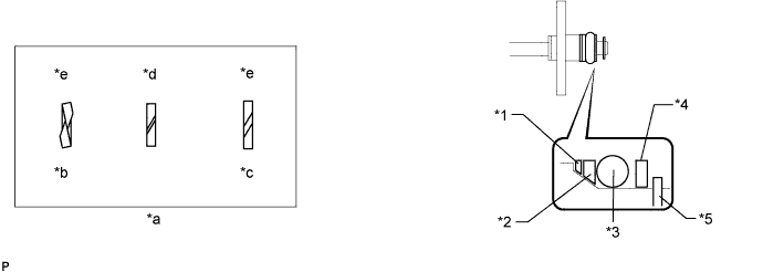
Text in Illustration *a Normal *b Protruding *c Deformed *d CORRECT *e INCORRECT After installing the seals, check that they are not scratched, deformed or protruding from the injector groove.
Note
If a seal is scratched, deformed or protruding from the groove, replace it with a new one.
-
-
INSTALL FUEL INJECTOR ASSEMBLY
-
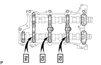
Install a new O-ring, new backup rings (No. 1, No. 2 and No. 3) and new E-ring to the fuel injector as shown in the illustration.
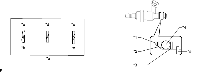
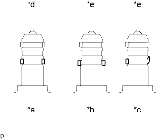
Text in Illustration *1 No. 1 Backup Ring *2 No. 2 Backup Ring *3 No. 3 Backup Ring *4 O-Ring *5 E-Ring - - *a Alignment Opening *b Overlapped *c Stretched *d CORRECT *e INCORRECT - - Note
-
Check that there is no foreign matter or damaged areas in the O-ring groove of the injector.
-
Check that the No. 1 and No. 2 backup rings are installed in the correct direction.
-
Make sure that the backup rings and O-ring are installed in the correct order.
-
Check that the alignment openings of the backup rings are not overlapped or stretched as shown in the illustration.
-
After installing the O-ring, check that it is not contaminated with foreign matter and is not damaged.
-
-
Install the injector nozzle holder clamp.
-
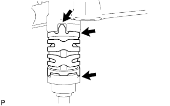
Apply gasoline to the O-ring. Install the nozzle holder clamp by aligning the protruding part of the clamp to the notch of the delivery pipe.
Note
-
Make sure that there is no gap between the delivery pipe and clamp.
-
Check that there is no foreign matter or damage to the injector insertion hole of the delivery pipe.
-
Insert the injector straight into the delivery pipe without tilting it.
-
-
-
INSTALL FUEL DELIVERY PIPE SUB-ASSEMBLY
-
Install a new injector vibration insulator to the cylinder head.
-
Apply lubricant to the installation hole of the injector.
-
Text in Illustration *1 Nut can be attached Insert the stud bolt into the fuel delivery pipe until the screw threads protrude enough so that a nut can be attached.
Note
-
If an injector is dropped or the tips of the injectors are struck, replace it with a new one.
-
Check that there is no foreign matter or damage to the injector insertion hole of the delivery pipe.
-
When inserting the fuel delivery pipe, push it in evenly without tilting it.
-
-
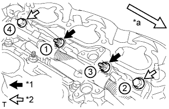
Text in Illustration *1 Nut *2 Bolt *a Front Install the No. 1 fuel delivery pipe by uniformly tightening the 2 bolts and 2 nuts in several passes in the order shown in the illustration.
- Torque:
- 26 N*m { 265 kgf*cm, 19 ft.*lbf }
-
Connect the 3 injector connectors and 2 wire harness clamps.
-
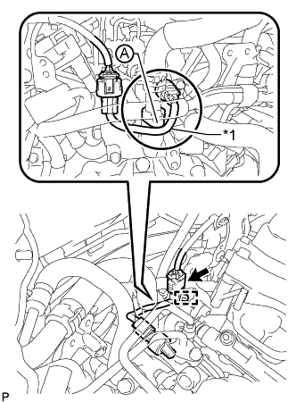
Text in Illustration *1 Wire Harness Connect the fuel pressure sensor connector and attach the clamp.
Note
-
Make sure the wire harness of the fuel pressure sensor passes under the area labeled A as shown in the illustration.
-
Do not pull the wire harness of the fuel pressure sensor excessively.
-
-
-
INSTALL NO. 2 FUEL DELIVERY PIPE SUB-ASSEMBLY
-
Install new injector vibration insulators to the cylinder head.
-
Apply lubricant to the installation holes of the injectors.
-
Text in Illustration *a Nut can be attached Insert the stud bolt into the delivery pipe until the screw threads protrude enough so that a nut can be attached.
Note
-
If an injector is dropped or the tips of the injectors are struck, replace it with a new one.
-
Check that there is no foreign matter or damage to the injector insertion hole of the delivery pipe.
-
When inserting the fuel delivery pipe, push it in evenly without tilting it.
-
-
Text in Illustration *1 Nut *2 Bolt *a Front Install the No. 2 fuel delivery pipe by uniformly tightening the 2 bolts and 2 nuts in several passes in the order shown in the illustration.
- Torque:
- 26 N*m { 265 kgf*cm, 19 ft.*lbf }
-
Connect the 3 injector connectors and 3 wire harness clamps.
-
-
INSTALL NO. 3 FUEL PIPE SUB-ASSEMBLY
-
Install new O-rings, new backup rings (No. 1, No. 2 and No. 3) and new E-rings to the No. 3 fuel pipe as shown in the illustration.
Text in Illustration *1 No. 1 Backup Ring *2 No. 2 Backup Ring *3 O-Ring *4 No. 3 Backup Ring *5 E-Ring - - *a Alignment Opening *b Overlapped *c Stretched *d CORRECT *e INCORRECT - - Note
-
Check that there is no foreign matter or damaged areas in the O-ring groove of the injector.
-
Check that the No. 1 and No. 2 backup rings are installed in the correct direction.
-
Make sure that the backup rings and O-ring are installed in the correct order.
-
Check that the alignment openings of the backup rings are not overlapped or stretched as shown in the illustration.
-
After installing the O-ring, check that it is not contaminated with foreign matter and is not damaged.
-
Check that the fuel pipe installation end is not contaminated with foreign matter and is not damaged.
-
-
Text in Illustration *a No Gap 
Front Apply gasoline to the O-ring.
-
Press the fuel pipe and delivery pipe together by hand until there is no gap between them. Then install the No. 3 fuel pipe with the 4 bolts.
- Torque:
- 10 N*m { 102 kgf*cm, 7 ft.*lbf }
Note
Do not install the No. 3 fuel pipe at an angle.
-
-
INSTALL REAR WATER BY-PASS JOINT
-
Install 2 new gaskets and a new O-ring.
Tech Tips
Apply soapy water to the O-ring.
-
Install the water by-pass joint with the 2 bolts and 4 nuts.
- Torque:
- 10 N*m { 102 kgf*cm, 7 ft.*lbf }
Note
Be careful that the O-ring does not get caught between the parts.
-
-
INSTALL VALVE STEM CAP
-
Apply a light coat of engine oil to the valve stem caps.
-
Install the 24 valve stem caps to the cylinder head.
Note
Install the valve stem cap at the same place it was removed from.
-
-
INSTALL VALVE LASH ADJUSTER ASSEMBLY
-
Inspect the valve lash adjuster Click here.
-
Install the 24 valve lash adjusters to the cylinder head.
Note
Install the lash adjuster at the same place it was removed from.
-
-
INSTALL NO. 1 VALVE ROCKER ARM SUB-ASSEMBLY
-
Apply engine oil to the lash adjuster tips and valve stem cap ends.
-
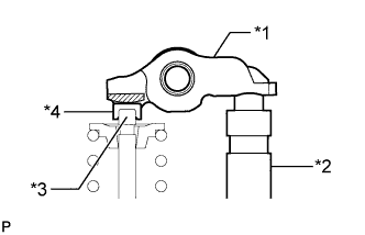
Text in Illustration *1 Valve Rocker Arm *2 Lash Adjuster *3 Valve Stem *4 Valve Stem Cap Install the 24 No. 1 valve rocker arms as shown in the illustration.
Note
Install the No. 1 valve rocker arm at the same place it was removed from.
-
-
INSTALL NO. 1 CHAIN VIBRATION DAMPER
-
Install the chain vibration damper with the 2 bolts.
- Torque:
- 23 N*m { 229 kgf*cm, 17 ft.*lbf }
-
-
INSTALL NO. 2 CHAIN VIBRATION DAMPER
-
Install the 2 chain vibration dampers.
-
-
INSTALL NO. 3 CAMSHAFT SUB-ASSEMBLY
-
Apply a light coat of engine oil to the No. 3 camshaft journals and camshaft housing sub-assembly LH.
-
Install the No. 3 camshaft sub-assembly to the camshaft housing sub-assembly LH.
-
-
INSTALL NO. 4 CAMSHAFT SUB-ASSEMBLY
-
Apply a light coat of engine oil to the No. 4 camshaft journals and camshaft housing sub-assembly LH.
-
Install the No. 4 camshaft sub-assembly to the camshaft housing sub-assembly LH.
-
-
INSTALL CAMSHAFT BEARING CAP (for Bank 2)
-
Apply engine oil to the camshaft bearing caps.
-
Make sure of the marks and numbers on the camshaft bearing caps and place each in the proper position and direction.
-
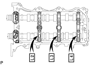
Temporarily tighten the 8 bolts in the order shown in the illustration.
- Torque:
- 10 N*m { 102 kgf*cm, 7 ft.*lbf }
-
-
INSTALL CAMSHAFT HOUSING SUB-ASSEMBLY LH
-
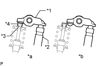
Text in Illustration *1 Valve Rocker Arm *2 Lash Adjuster *3 Valve Stem *4 Valve Stem Cap *a CORRECT *b INCORRECT Make sure that the No. 1 valve rocker arm is installed as shown in the illustration.
-
Text in Illustration *1 Seal Packing Apply seal packing in a continuous line as shown in the illustration.
Seal packing Toyota Genuine Seal Packing Black, Three Bond 1207B or equivalent Seal diameter 3.5 to 4.0 mm (0.138 to 0.158 in.) Note
-
Remove any oil from the contact surface.
-
Install the camshaft housing sub-assembly LH within 3 minutes.
-
Do not start the engine for at least 2 hours after installation.
-
-
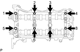
Text in Illustration *1 Knock Pin *a IN *b EX Install the camshaft housing sub-assembly LH and tighten the 13 bolts in the order shown in the illustration.
- Torque:
- 28 N*m { 286 kgf*cm, 21 ft.*lbf }
Note
-
When installing the camshaft housing sub-assembly LH, it is necessary to correctly position the camshafts as shown in the illustration. Failure to correctly position these parts may result in damage due to contact between the pistons and valves. If a camshaft is rotated with a piston at TDC, valve contact will occur.
-
If any of the bolts are loosened during installation, remove the camshaft housing sub-assembly LH, clean the installation surfaces, and reapply seal packing.
-
If the camshaft housing sub-assembly LH is removed because any of the bolts are loosened during installation, make sure that the previously applied seal packing does not enter any oil passages.
-
Tighten the 8 bolts in the order shown in the illustration.
- Torque:
- 16 N*m { 163 kgf*cm, 12 ft.*lbf }
-
-
INSTALL CAMSHAFT
-
Apply a light coat of engine oil to the camshaft journals and camshaft housing sub-assembly RH.
-
Install the camshaft to the camshaft housing sub-assembly RH.
-
-
INSTALL NO. 2 CAMSHAFT
-
Apply a light coat of engine oil to the No. 2 camshaft journals and camshaft housing sub-assembly RH.
-
Install the No. 2 camshaft to the camshaft housing sub-assembly RH.
-
-
INSTALL CAMSHAFT BEARING CAP (for Bank 1)
-
Apply engine oil to the camshaft bearing caps.
-
Make sure of the marks and numbers on the camshaft bearing caps and place each in the proper position and direction.
-
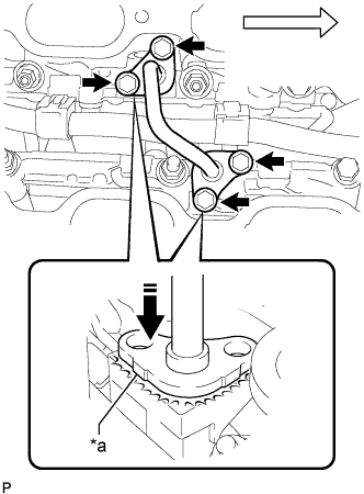
Temporarily tighten the 9 bearing cap bolts in the order shown in the illustration.
- Torque:
- 10 N*m { 102 kgf*cm, 7 ft.*lbf }
-
-
INSTALL CAMSHAFT HOUSING SUB-ASSEMBLY RH
-
Text in Illustration *1 Valve Rocker Arm *2 Lash Adjuster *3 Valve Stem *4 Valve Stem Cap *a CORRECT *b INCORRECT Make sure that the No. 1 valve rocker arm is installed as shown in the illustration.
-
Text in Illustration *1 Seal Packing Apply seal packing in a continuous line as shown in the illustration.
Seal packing Toyota Genuine Seal Packing Black, Three Bond 1207B or equivalent Seal diameter 3.5 to 4.0 mm (0.138 to 0.158 in.) Note
-
Remove any oil from the contact surface.
-
Install the camshaft housing sub-assembly RH within 3 minutes.
-
Do not start the engine for at least 2 hours after installation.
-
-
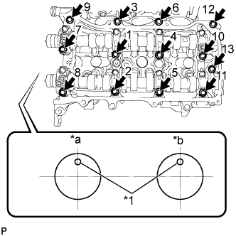
Text in Illustration *1 Knock Pin *a EX *b IN Install the camshaft housing sub-assembly RH and tighten the 14 bolts in the order shown in the illustration.
- Torque:
- 28 N*m { 286 kgf*cm, 21 ft.*lbf }
Note
-
When installing the camshaft housing RH, it is necessary to correctly position the camshafts as shown in the illustration.
Failure to correctly position these parts may result in damage due to contact between the pistons and valves. If a camshaft is rotated with a piston at TDC, valve contact will occur.
-
If any of the bolts are loosened during installation, remove the camshaft housing sub-assembly RH, clean the installation surfaces, and reapply seal packing.
-
If the camshaft housing sub-assembly RH is removed because any of the bolts are loosened during installation, make sure that the previously applied seal packing does not enter any oil passages.
-
Tighten the 9 bolts in the order shown in the illustration.
- Torque:
- 16 N*m { 163 kgf*cm, 12 ft.*lbf }
-
-
INSTALL NO. 3 CHAIN TENSIONER ASSEMBLY
-
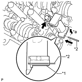
Text in Illustration *1 Plunger *2 Pin *a Push Install the No. 3 chain tensioner assembly with the bolt.
- Torque:
- 21 N*m { 214 kgf*cm, 15 ft.*lbf }
-
While pushing in the tensioner, insert a pin of 1.0 mm (0.0394 in.) diameter into the hole to hold it.
-
-
INSTALL CAMSHAFT TIMING GEARS AND NO. 2 CHAIN (for Bank 2)
-
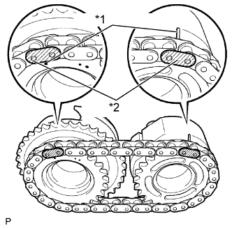
Text in Illustration *1 Timing Mark *2 Mark Plate Align the mark plates (yellow) with the timing marks of the camshaft timing gear assemblies as shown in the illustration.
-
Apply a light coat of engine oil to the bolt threads and bolt-seating surface.
-
Align the knock pin of the camshaft with the pin hole of the camshaft timing gear assembly. Install the camshaft timing gear assembly and camshaft timing exhaust gear LH with the No. 2 chain sub-assembly installed.
-
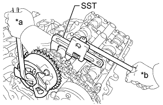
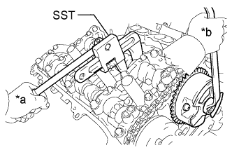
Text in Illustration *a Turn *b Hold Using SST to hold the hexagonal portion of each camshaft, tighten the flange bolts of the camshaft timing gear assembly and the camshaft timing exhaust gear assembly LH.
- SST
- 09922-10010
- Torque:
- 100 N*m { 1020 kgf*cm, 74 ft.*lbf }
-
Remove the pin from the No. 3 chain tensioner assembly.
-
-
INSTALL NO. 2 CHAIN TENSIONER ASSEMBLY
-
Text in Illustration *1 Plunger *2 Pin *a Push Install the No. 2 chain tensioner assembly with the bolt.
- Torque:
- 21 N*m { 214 kgf*cm, 15 ft.*lbf }
-
While pushing in the No. 2 chain tensioner assembly, insert a pin of 1.0 mm (0.0394 in.) diameter into the hole to hold it.
-
-
INSTALL CAMSHAFT TIMING GEARS AND NO. 2 CHAIN (for Bank 1)
-
Text in Illustration *1 Timing Mark *2 Mark Plate Align the mark plates (yellow) with the timing marks of the camshaft timing gear assemblies as shown in the illustration.
-
Apply a light coat of engine oil to the bolt threads and bolt-seating surface.
-
Align the knock pin of the camshaft with the pin hole of the camshaft timing gear assembly. Install the camshaft timing gear assembly and camshaft timing exhaust gear assembly with the No. 2 chain sub-assembly installed.
-
Text in Illustration *a Turn *b Hold Using SST to hold the hexagonal portion of each camshaft, tighten the flange bolts of the camshaft timing gear assembly and the camshaft timing exhaust gear assembly RH.
- SST
- 09922-10010
- Torque:
- 100 N*m { 1020 kgf*cm, 74 ft.*lbf }
-
Remove the pin from the No. 2 chain tensioner assembly.
-
-
INSTALL CHAIN SUB-ASSEMBLY
-
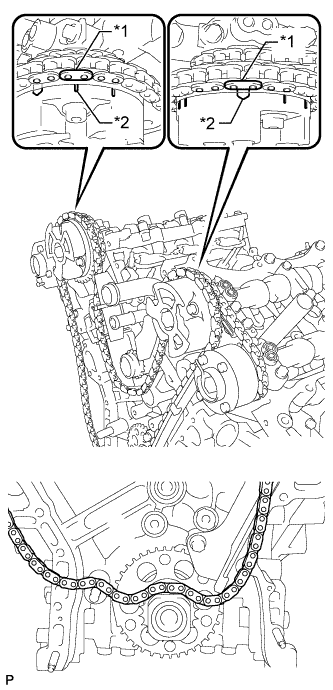
Text in Illustration *1 Mark Plate (Orange) *2 Timing Mark Align the mark plates and timing marks as shown in the illustration and install the chain.
Tech Tips
The camshaft mark plates are orange.
-
Rest the chain on top of the crankshaft.
-
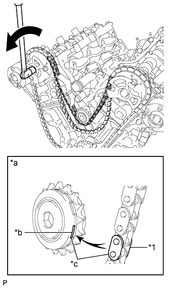
Text in Illustration *1 Chain Plate *a When idle sprocket is reused *b Mark *c Align Turn Turn the camshaft timing gear assembly on the RH bank counterclockwise to tighten the chain between the banks.
Note
When the idle sprocket is reused, align the chain plate with the mark where the plate had been in order to tighten the chain between the banks.
-
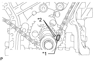
Text in Illustration *1 Mark Plate (Yellow) *2 Timing Mark Align the mark plate and timing mark as shown in the illustration and install the chain onto the crankshaft timing sprocket.
Tech Tips
The crankshaft mark plate is yellow.
-
Temporarily tighten the pulley set bolt.
-
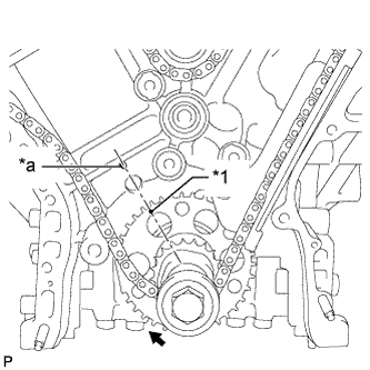
Text in Illustration *1 Timing Mark *a Center Line Turn Turn the crankshaft clockwise to set it to the RH block bore center line (TDC/compression).
-
-
INSTALL CHAIN TENSIONER SLIPPER
-
Install the chain tensioner slipper.
-
-
INSTALL NO. 1 CHAIN TENSIONER ASSEMBLY
-

Text in Illustration *1 Stopper Plate *2 Plunger Move the stopper plate upward to release the lock, and push the plunger deep into the tensioner.
-
Move the stopper plate downward to set the lock, and insert a pin of 1.27 mm (0.0500 in.) diameter into the hole of the stopper plate.
-
Install the chain tensioner with the 2 bolts.
- Torque:
- 10 N*m { 102 kgf*cm, 7 ft.*lbf }
-
Remove the lock pin of the chain tensioner.
-
-
INSPECT VALVE TIMING
-
Check the camshaft timing marks.
Note
-
Check each timing mark from a viewpoint directly inline with the center of the camshaft and the timing mark on each camshaft timing gear.
-
If the timing marks are checked from any other viewpoint, the valve timing may appear misaligned.
-
-
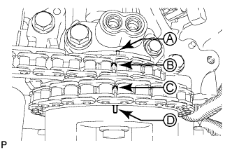
Check that each camshaft timing mark is positioned as shown in the illustration.
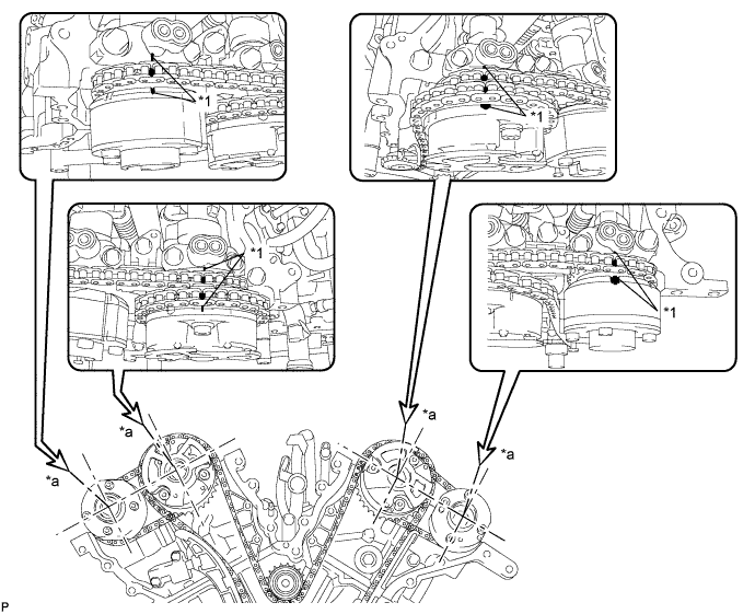
Text in Illustration *1 Timing Mark - - *a Viewpoint - - Tech Tips
For the intake camshaft:
Be sure to check mark A at the point when marks B, C, and D are positioned in line. If the marks are checked from any other viewpoint, they cannot be checked correctly.
-
If the valve timing is misaligned, reinstall the timing chain.
-
Remove the pulley set bolt.
-
-
POUR ENGINE OIL
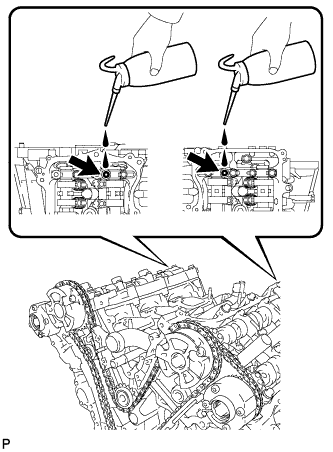
Tech Tips
Before installing the cylinder head cover, pour engine oil into the locations shown in the illustration.
-
INSTALL TIMING CHAIN COVER SUB-ASSEMBLY